Generative
Design of Membrane Concrete Grid Shells
Dipl. Ing. Gregor
Zimmermann
Department
Architecture Urban and Landscape Design, Sub department of Structure Design
University of Kassel, Germany.
e-mail:
zimmermann@architektur.uni-kassel.de
Abstract
Membrane Concrete Grid Shells (MBG - Membran Beton Gitterschalentragwerke)
are a new invention of the department Structural Design at the FB6
Architecture, Urban- and Landscape Design - University Kassel. It is a
redeveloped construction method based on air-halls, airforms and grid shells of
ultra high performance concrete (UHPC) that allows a very fast and cost
effective erection of wide span concrete grid shells. Because of the very
simple construction and the high compression and flexural strength of the
concrete nearly every kind of concrete grid mesh on a form-giving surface is
possible. Construction, dimension and shape rules could be found to generate
those MBG constructions. Optimization methods to minimize and optimize the
structure are simple and could easily be integrated. Thus generative design
could be a strong tool respective method to generate a large variation of cost
effective and architectural appealing wide span concrete grid shells.
The paper will give a short insight to the MBG invention and a
theoretical description of how Membrane Concrete Grid Shells could be
generatively developed with tools like the Finite Element Software ANSYS, CAD
Systems, Optimization methods and simple hand based rules. It will show, that
generative design could be an innovative tool for structural engineers to
generate a large variation of constructions in a large solution space that
would not be possible by the classical work methods of engineers.
Keywords: Membrane Concrete Grid Shell, Generative Design, structure
design, finite element system, ANSYS, Topology Optimization, Soft Kill Option,
air-inflated hall, shell, grid, membrane chamber, form finding, bionic.
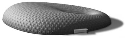
fig. 1: Membrane Concrete Grid Shell rendering
1 The Invention
The main idea was to combine different construction or assembly types to
get a new structure and construction method. Main focus was the use of new
materials and technologies to point out their technical advantages as well as
the development of cost-effective construction systems. Secondarily an
architectural appealing system should be the result of the new construction
system.
In the last decade some new technologies in the building industry had
been developed but not often used jet. New concrete types like UHPC (Ultra High
Performance Concrete) that could absorb large pressure and tension forces or
Membranes with new surface coatings that are more resistant against
environmental influences.
The Idea of combining pneumatic moulds and concrete shell structures is not new. Innovative is the use of UHPC that includes the reinforcement in combination with inflated double-layered membrane structures, which are connected to each other directly or with membrane flaps. Those are arranged in a special way that continuous chambers are created which could be filled with UHPC or another self-hardening material. The result is a Membrane Concrete Grid Shell, particularly a thin wide spanning concrete grid shell with nearly any user-defined grid respective mesh with a curved shape.
1.1 Basic Construction Systems
The basic construction systems for MBG structures are air-halls,
airforms and thin concrete shells. Inflated structures in the building industry
are known since 1918. F.W. Lanchester developed a patent "An Unproved
Construction for Field Hospitals, Depots, and like purposes" [5]. Since
than a lot of pneumatic structures had been build. Pioneers like Frei Otto and
Walter Bird evolved a lot of forms and membrane materials. With the
introduction of new technologies and computer-aided design totally new
pneumatic structures and shapes are possible like the NouvelleDestination
Pavilion at the EXPO.02 that was engineered by IPL (Ingenieurplanung Leichtbau
GmbH - now FormTL).
The first concrete domes with the use of airforms had been built by
Wallace Neff [7] in 1940. It was a single layer dome membrane. The
reinforcement had to be fixed from outside and was covered with shotcrete. This
kind of construction method is not substantially changed till today. The
organisation Monolithic Dome Institute, Texas/USA is still using this method
with advanced construction details. 1987 Werner Sobek developed mathematical
methods to calculate inflatable structures under full fluid concrete load and
form finding air supported concrete shells [9].
Different architects and engineers developed double-layer membrane moulds but only a few of them realized projects. Dante Bini, an Italian architect, builds the most known concrete shells with this method since 1965 [9, 2].
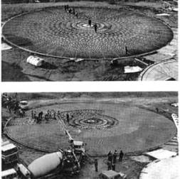
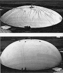
fig. 2: Dante Bini's shell construction [2]
The disadvantages of all those methods are monolithic shells that had to
be opened afterwards and their simple geometrical shape.
1.2 Construction Components
Based on those known construction systems and with the use of modern
technologies, materials and software the Membrane Concrete Grid Shells had been
invented as described before.
Concrete in a large variety is obtainable. Relating to MBG structures,
concrete with integrated reinforcement should be used. The reduction of weight
respective concrete load during the assembly of the MBG inflated system and the
minimization of concrete for structural, architectural and design aspects are
the main idea. For this, the UHPC (Ultra High Performance Concrete), which is
developed and adapted for the MBG structures by a research cooperation of the
University Kassel, is the best choice. UHPC is a self-compressing concrete with
a high Young's module and a high permissible strength. Among other things, the
integrated steel fibres achieve this property. The compressive strength of UHPC
could be between 200N/mm² and 400N/mm². The Young's module is about 55000
N/mm². Splitting tensile strength is up to 17 N/mm² and bending stiffness 39
N/mm² [1, 8]. Further values are W/b=0.2 and w/z=0.28. These are approximately
given specifications that could be changed for the needs of MBG structures. The
material could be pumped with a piston pump, thus allows a simple handling.
Material for air-halls or airforms could be PTFE Foils, PTFE coated
fibre fabrics and PVC coated Polyester fabrics or ETFE Foils. For large
inflatable structures with high loads PVC coated Polyester fabrics are the
common membrane types. Five classes, from TYP I with low permissible stress
(3000 N/5cm) up to TYP V with high permissible stress (9800 N/5cm) are
available [6]. Regarding to MBG structures, the internal pressure, the concrete
load and the resulting tensile stress is very low. Depending on the size of the
structure it is possible to use membranes TYPE II or TYPE III. The connection
respective membrane details are very simple and easy to manufacture. High
frequency weldings or steel clamping plates are very simple and cost-effective.
In combination with hook and loop fasteners or other zip connections the
membrane could be manufactured removable.
2 Construction Theory & Design Rules
Steel, wood or bamboo is often used to build grid shell structures.
Concrete is an exception, finally not of the material itself, but because of
the complex formwork. The cost of a concrete grid shell is out of all
proportion to the structure.
So there is nearly no experience with monolithic concrete grid shells. A
lot of questions are open and interesting research topics could be defined. An
important question is the stability of such a concrete grid shell under dynamic
loads during assembly like dynamic wind loads and the stability after
completion through e.g. earth quakes. Especially because of the atypical shape
and mesh of architectural designed concrete grid shells that could be found
with special optimization algorithms as there are structure optimization, CAO
(computer aided optimization), SKO (Soft Kill Option), evolutionary design or
generative design which is the topic of this paper.
Focused on generative design it is necessary to analyse the construction and its components to understand the functioning of the structure and to find rules, properties and parameters for the concrete grid shell.
2.1 Moulds & Membrane Chamber System
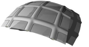
fig. 3: Example for a membrane concrete chamber system
The airform or mould exists
out of two layers membrane, connected via direct welding or flap (fig. 3). Space between those weldings will act as concrete
chambers. The mesh could vary on the surface and generate different patterns.
Those patterns are arbitrary. Depending on the curvature of the surface, the
mesh could be adapted. With this simple concept it is possible to generate
concrete grid shells within a large solution space. The final geometry of the
concrete chambers respective membrane moulds must be recognized for the
patterning of the airform. Wrinkles could weaken the concrete profile
extremely. To produce that complex double-layered membrane moulds demands a
high technical understanding and production facilities are required. Generally
it is possible to build almost every pneumatic supported form.
2.2 Construction Assembly
The Figure (fig.
4) shows the assembling of the MBG system on side. The
double-layered membrane is outspread on the ground and the edges fixed at the
circumferential foundation. The System will be erected by inflating the
airform. After the inner maximum pressure is achieved, the second membrane
chamber system could be inflated. This will simplify the handling and reduces
deformations through wind. Concreting sections from the foundations to the top
or pole will be defined and filled with UHPC in a special order and given time
steps. The dimensions on these concreting sections are depending on the size of
the whole MBG construction and the imperfections.
This remark represents the simple idea behind the construction. But in the next paragraph you will see the complexity of the interdependencies for assembly, airform, details, concrete grid shell and the complete structure.


fig. 4: Scheme of MBG construction assembly
2.3 Interdependencies
Several physical states of the construction will appear. Particularly the UHPC will change his properties during time extremely, from a very fluent to a high compressed material. These Properties must be considered for designing airforms and concrete grid structures. Also the airform itself demands a special geometry and construction to work as concrete mould. The grid shell must fulfil several static functions to be stable, which depends on the geometry of the grid mesh and the airform. So every construction part or detail is associated with other parts or functions as roughly shown in fig. 5 and described in the following paragraphs.
airform The shape of the airform itself is given by the patterns of the
membrane and the inner pressure. The deformation of the airform
("pre"shape) is a result of the local concrete dead load in the
chamber system. Reshaping counteracts the deformation of the final concrete
grid shell ("final"shape).
chamber-system The geometry of the chamber system respective the
mesh depends on different possible parameters or usages. The mesh could be
shaped for architectural, design or statical interests and is totally free in
its geometry. Only two boundary condition must be fulfilled a) the chamber
system must be continuous to get a grid shell structure b) the complete
concrete grid shell must be stable.
grid-shell In this case a concrete grid shell could be defined as
a monolithic concrete shell with holes in its surface. Their size respective
the "mesh" geometry is arbitrary. The thickness off the shell
respective grid could vary and depends on the minimal statical requirements for
the stability of the grid shell. These properties are directly linked to the
shape of the whole grid shell.
concrete UHPC (Ultra High Performance Concrete) is an almost
new material. It is self-compacting and could take very high pressure, tension
and bending loads. The composition of the material could be adapted to the
statical requirements of the grid shell. The thickness of the grid depends on
the material composition.
imperfections During concreting in sections the dead load of the
concrete deforms the airform. With this comes the deformation of the final
concrete grid shell. Changing the inner pressure of the airform counteracts the
imperfections but with this comes another "pre"shape of the airform
to get the "final"shape of the concrete grid shell.
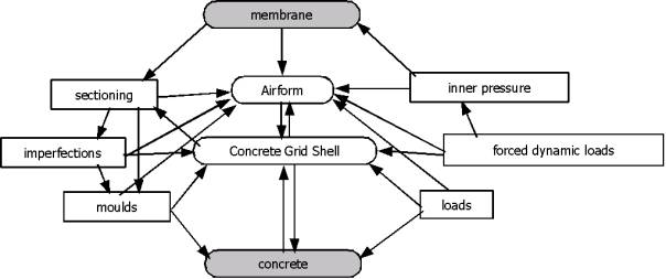
fig. 5: Excerpt of MBG construction interdependencies
3 Generative Design of MBG Shells
At first the sense of generative design with respect to membrane
concrete grid shell structures must be defined. The simplest definition could
be:
Generative Art refers to any art practice where the artist uses a
system, such as a set of natural language rules, a computer program, a machine,
or other procedural invention, which is set into motion with some degree of
autonomy contributing to or in a completed work of art. Philip Galanter [4]
C.Soddu gives a more complex description of generative art or design in
relation to architecture. The idea could be seen as artificial DNA with a set
of transformation rules that must be setup for the clients needs. Thru this it
becomes a dynamic auto-organizing system with an increasing complexity because
of cycling results. The result will be the generation of endless scenarios that
allows the client to select and choose among different proportions. With the
feedback of the client the DNA could be adapted and the process could restart
[10].
The design process is always an interactive process of creating samples,
comparing, modifying, making incremental improvements and so on. It is a kind
of evolutionary process with genetic variation and natural selection, done
manually. Through computer technology it is possible to automate parts of this
process with genetically inspired algorithms. But the variation of the
solutions related to structures is often very restricted because of strict
boundary conditions [11].
Generally generative design, in this case, should be seen as additional
design tool that independently determines good solutions for the structural and
architectural design of MBG shells and as decision facility for architects or
designers with the result of possible new and maybe unpredictable solutions.
This is possible because of the clear structural problem and the direct
mathematical results calculated by finite element systems. These structural
properties and the thereby essential shape of the structure could be seen as
fitness function that allows to deselect senseless constructions out of a large
variation of solutions. On the other hand the costs of buildings and structures
are very important for the building industry and could be an indicator for a
further fitness function.
To define the generative design process, the aim of the whole procedure must be clear and analysed. As shown in the previous paragraphs there are many parameters, boundary conditions, fitness and objective functions.
3.1 Objective Function
In architecture and structural design the main aim are cost effective
constructions. Normally those constructions or structures are very simple and
don’t fit to the architecture of the building in geometry and design. The
engineering and designing of vary of structures for one building is very
expensive because it is done manually. The engineers, architects or designers
themselves are having ideas in mind; so they will not change their concept or
design intensely and thereby generate a small vary of similar solutions. They
will just find a local good solution for their problem.
Generative design systems are able to generate arbitrary good solutions
for a problem by combining, solving, analysing and resolving a problem
autonomous. But therefore all parameters, boundary conditions, fitness
functions and objective functions must be defined and implemented in the system
by the designer.
The aim for the design of Membrane Concrete Grid Shells should be finding cost effective and architectural appealing solutions by a large vary of shapes and meshes. To lose not all sense of perspective the illustration of the complete problem will be strongly simplified for this proceeding. The variation of shapes is a mathematical and related to airforms complex problem that will be unnoticed in the further descriptions. So the objective function (1) will only have one parameter.
![]() (1)
(1)
3.2 Parameters
Now the definition of cost effective must be analysed to find the
required parameters. Minimizing the costs means minimizing the concrete
structure that means minimizing the internal forces, bending moments and
maximizing the stability of the structure by performing the architectural
appealing. This could be done by optimizing the mesh resp. concrete grid,
optimizing the concrete chamber resp. moulds, optimizing the thickness of the
grid shell and or optimizing the composition of the Ultra High Performance
Concrete. Also the re-shaping or adapting the shell geometry of the given
structure could perform the stability and reduction of structure. So cost
effectiveness (2) is a function of four parameters.
![]() (2)
(2)
![]() (3)
(3)
![]() (4)
(4)
![]() (5)
(5)
![]() (6)
(6)
These four parameters are related to each other and could be used
reverse. So maximizing the stability could be defined as function of internal
forces and the grid shape. The internal forces could be seen as function of the
material composition and loads. One direct solution is not possible and in the
case of generating generative structures not desired. This causes a very large
solution space with any kind of solution that could not be controlled. Because
of these relations it is necessary to find fitness functions respective design
rules for finding good solutions. Or in other words: a pre-selection of good
solutions.
3.3 Fitness Functions
Minimizing the structure by reducing internal forces is a perfect
fitness function. Two tools could be used for this a) Topology Optimization and
the b) Soft Kill Option.
"Topology Optimization is an shape or layout optimisation with the
goal of finding the best use of material for a structure, body or surface such
that the objective (fitness) function takes on a maximum or minimum value to
given constrains such as volume reduction... Standard formulation for Topology
Optimisation is the problem of minimising the structural compliance while
satisfying a constraint on the volume V() of the structure. Then minimising
compliance (Young's modulus) means maximising the global stiffness of the
structure." [11] See fig.
6 for a simple topology optimized shell.
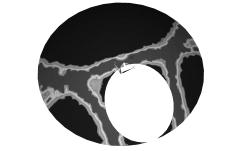
fig. 6: Simple topology optimized
Shell with an hole at the front. The bright areas could be defined as primary
structure. A secondary structure must be defined in further optimization
shapes.
With the Soft Kill Option all lazy finite elements could be killed or
deactivated. "If the procedure is functioning well, the good elements are
becoming stronger and stronger while the bad elements are getting weaker and
weaker. At the end, the bad elements will not take any loads because of their
very low Young's modulus." [11] Those elements could be deactivated. The
pure statical structure will be left.
3.4 Design Rules
Another method for
minimizing the structure could be re-shaping the already given surface by
adding folds and buckles to stabilise the structure. For Example, a single
curved surface will be much more stable if the edges are bend in a way that the
single curved surface will be modified into a double curved surface (see fig. 7).
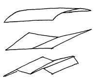
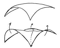
fig. 7: Folding and bending to increase structure stiffness
In this case there are several design rules, distinguishable into
different geometrical and structural respective material parametric
dependencies. An excerpt is shown in fig.
8. The shape of the MBG structure could be changed
directly thru bending, folding, buckling or displacing. Changing the Young’s
modulus, the thickness or section of profiles and the mesh respective grid is
influencing the "hardware" accordingly the structure and is interacting
with the shape. These characteristics concerning interdependencies are already
mentioned in paragraph 2.3.
fig. 8: Excerpt of design rules
Using the design rules is another challenging research assignment
because the order of applying those rules could change the results of the
generation according the structure. For example changing the thickness of a
shell would cause lower forces in the structure but would maybe prevent the
autonomous folding of the structure. Folding the structure at first will reduce
the forces in the structure and prevents maybe the autonomous thickening of the
structure. So the start policy of geometry and structure as well as the order
of using the rules is important and could contribute the good or bad results.
Parameters and rules for the generative design process must be defined.
3.5 Generative Design Process
Aforementioned the order of using design rules for structures could be
very important for the quality and the amount of the results. Depending on the
generative design approach, the fitness and objective functions it must be
proofed whether the design rules must be used in a serial order or could be
used simultaneous.
A hierarchic structure will be the mapping of using rules in serial order. This makes it easy to find chain structures for the generative design process, which will benefit the solution. But only those 8 design rules (fig. 8) will cause possible 40320 combinations in one process cycle that must be proofed. According to the complexity of MBG structures one process cycle is not sufficient. Approximately ten process cycles[1] must be calculated to get good intelligent results. Projected to ten cycles there will be 7.16E118 combinations with the trial and error method. This is not practicable particularly if one FEM calculation of a larger structure needs up to 10 minutes. So it is essential to evaluate a strategy for the order of design rules to reduce the amount of possible combinations.
fig. 9: Generative Design process
The usage of several design
rules at the same time will improve the solution speed but should only be
utilized if dependencies are not relevant and the system very easy. So
different design rules could be combined and used parallel to get results but
this could be seen as a trial-and-error process. Drawing conclusions after some
process cycles according to an intelligent design strategy is not possible.
Regarding the previous mentioned background the MBG structures should be
generated with the serial usage of design rules. As reflected from small test
series the most effective way is to change geometry and finally the thickness
or material of a structure. With this knowledge the possible amount of design rule
combinations could be reduced dramatically. So fig. 9 shows the simplified generative design process for
MBG structures.
4 Conclusions
As described before the process of generating and optimizing a structure
regarding all boundary conditions, fitness and object functions as well as
architecture and design is very complex. To fulfil all conditions requires an
ambitious work, if an engineer does it manually. The output is then hardly
reduced to one or two solutions and will take a lot of time.
Using Generative Design during the structure design process could be a
very effective method to get a lot of good results in a large solution-space,
and solutions that maybe could be beyond any inconceivability and will give the
engineer, architect or designer new inspirations. Spin-off is not only the
large amount of solutions but also the economy of time.
Generative Design, applied to Membrane Concrete Grid Shells points up
these effects. By defining the boundary conditions, design rules, fitness and
objective functions the structure and the aim of the design concept will be
clear. Implementing this knowledge into software is a large expense but will be
worthwhile thru the large amount of solutions and the economy of time. Once the
generative design process for an application is implemented it is possible to
repeat or start new structure designs anytime. So far the method described in
this paper is almost theoretical. The implementation into ANSYS occurs
stepwise. First positive results and exemplary generative designed MBG
structures are created. But the greatest challenge is the interaction between
3D graphic software and the finite element software that is often not able to
cope with parametric geometrical properties. So at the moment some of the above
mentioned design rules and intermediate steps must be done manually. This is
creating needs on open software interfaces.
At least the MBG structures are only one field of application for
generative design on structure design. There are much more defiance’s like
frameworks, space frames, shells...
References
[1] Bornemann, Schmidt,
Fehling and Middendorf, Ultra-Hochleistungsbeton UHPC , Beton- und Stahlbetonbau, 2001 , 96 ,
458-467
[2] Dante Bini; BiniSystems, http://www.binisystems.com , 7/2004
[3] FormTl, NouvelleDestination, www.formtl.de, 3/2002
[4] Philip Galanter; What is Generative
Art? Complexity Theory as a Context for Art Theory , In GA2003, Proceedings of
the 6th international conference GENERATIVE ART 2003
[5] Lanchaster; Improvements in the
construction and Improvements in the construction and roofings of buildings for
Exhibitions and like Purposes, Patent,
GB000000145193A, 1919
[6] Jörg Minte; Das
mechanische Verhalten von Verbindungen beschichteter Chemiefasergewebe, Fakultät für Maschinenwesen, PhD Thesis, Fakultät für
Maschinenwesen,TH Aachen, Germany, 1981
[7] Wallace Neff; Improved method of
erecting shellform concrete structures , Patent,
US000002892239A, 1952
[8] M. Schmidt;
Ultra-Hochfester Beton - Planung und Bau der ersten Brücke mit UHPC in Europa;
Tagungsbeiträge zu den 3. Kasseler
Baustoff- und Massivbautagen, university
press, Kassel, 2003 , 5-20
[9] Werner Sobek; Auf
pneumatisch gestützten Schalungen hergestellte Betonschalen, Ursula Sobek Verlag, Stuttgart, 1987
[10] Celestino Soddu; Visionary Aesthetics
and Architecture Variations, In GA2003, Proceedings of the 6th
international conference GENERATIVE ART, 2003
[11] G. Zimmermann; Structure Optimization, BOD.DE, 2005 (Feb.)