Problems in the
Perception of Linear Perspective
Prof. Aleksandra Slahova, Dr.Paed
Department of Art, Daugavpils
University, Latvia.
e-mail: aleksa@dau.lv
Abstact
It is well know that the shape and size of objects
visually changes if the object’s distance from the viewer and the position of
the object change, but it needs specific theoretical training in the
construction of perspective. For these reasons, drawing three-dimensional
objects on the picture plane demands not only knowledge of their external
peculiarities, but also skills in matching the shape of objects to the
peculiarities of visual perception which allows us to represent objects
“truthfully”. However, this is one of the hardest tasks in drawing. It needs
specific theoretical training in the construction of perspective. A review of
textbooks and resource books on drawing published in different countries during
the last 30 years reveals that a body of rules for linear perspective has
evolved which is stable and interpreted similarly. However, explanations of the
practical implementation of one-point perspective are not quite logical. This
article covers some of the problems of the perception of perspective, and
offers methodical recommendation for implementing linear perspective in
training for drawing.
Keywords: historical treatise, perspective, linear perspective,
descriptive geometry, methodical recommendation.
Introduction
Many centuries ago western artists observed the
regularities of visual perception, and by the 15th century, Italian
artists had collected important experience in reproducing their observations by
means of drawing, painting, or sculpture. These were sufficient to allow the
structuring of the experience and knowledge in coherent system. This began the
science of explaining and theorizing certain forms of depiction related to the
visual perception of the world - “perspective”- meaning the ability to see
correctly. It was no accident that Giovanpaolo Lomazzo (1538-1588) once asserted,
that he would rather die than disregard the perspective [1].
Following of the “discovery” the area has been examined by scientists, psychologists, architects, and art educators who have theoretically investigated perspective which derived from the creative practice of Renaissance artists and was more precisely named as “linear perspective”. Changes occurred as the theories developed and were used and elaborated as practical recommendations for drawing.
Review of textbooks and other resources on drawing published in different countries during last 30 years shows that a body of rules for linear perspective has evolved and is stable where a range of authors maintain general agreement. However, there are some exceptions, e.g., the practical implementations of one-point perspective.
The first part of this investigation was introduced in my article in the International Journal of Art and Design Education, Vol.19.1. (England) [2].
This article deals with the different aspects of
studies of linear perspective continuing the discussion about the essence and
problems of world perception in perspective.
1. Linear
perspective
Linear perspective can be subdivided
into three types: one-point, two-point and three-point perspectives.
One-point perspective. Figure 1 illustrates how lines, which are
parallel to one another, and recede into the depth of the picture towards the
horizon, will all meet at one vanishing point on the horizon line [3].
Figure 1.
“Also, we have one-point perspective when both the height and width of an object are parallel to the picture plane” [4]. “In the exercise, …a number of boxes of various sizes and positions are drawn using the same perspective point. Notice that in all cases, the height and the width of the boxes are always parallel to the picture plane” [5].
Analogical definitions can be found also in a range
of textbooks [6].
Two-point perspective. Figure 2 illustrates that when two
or three sides of a cube are visible and all sides of the cube recede in
spatial depth, the lines are directed to two vanishing points [7].
Three-point perspective. Figure 3 shows that
when we view an object (e.g. a high building) from either a top view or a
bottom view, we are most likely viewing it in three-point perspective.
The point, where the vertical lines cross is the position of the third
vanishing point.
Figure 2.
Figure 3.
2.
One-point perspective
Object construction according to the rules of two-point perspective raises no particular doubts.
We will try to analyze more deeply the peculiarities of object depiction in one-point perspective, where one author give the following specific definition: “A rectangular-based solid … can be drawn by putting together all the planes created by the perspective rectangles. Thus, the front plane, which is parallel to the picture plane, can be drawn and the sides produced back from the corners to the vanishing point. Think of each side as a rectangular plane going back in space. The rectangular-based solid can also be shown to left or right of the vanishing point, revealing another side” [8].
In my opinion, the implementation of one-point perspective with the visible side plane has not been interpreted correctly. Let us examine the example of a drawing of a cube in a position where one side of the planes is visible and the horizontal edges of the front side do not have a vanishing point.
Schipanov, writing about one-point perspective construction methods notices: “For a cube which is positioned at an angle from the central visual ray one extra side plane always will be visible” and describing the construction of two-point perspective he gives the following definition: “In two-point perspective the position of cube’s lines of receding planes is directed towards two not one vanishing point” [9]. Attentive reading of both definitions raises the following doubts: if the cube is diverged on to one side of the central visual ray does not that means that the cube already is in a “two-point perspective” position?
Arnheim resolves this by the following explanation: to see the side planes of a physical object a viewer has to look from some side angle. In these conditions all sides, including the front side, have to appear distorted. When the frontal side is seen in the shape of a square this means that the viewer is looking at the object perpendicularly and that none of the side planes or top plane should be visible. By changing the angle of recession side planes become visible, and in this case it is not possible to see the frontal square [10].
Let us consider one more example about one-point perspective construction (Figure 4).
“Draw
two guidelines from the bottom outside corner of each front leg to the V.P. “(vanishing point). “This determines the width
of the back legs. Now, place two boxes on the table using the same vanishing
point” [11].
Figure 4 shows
that in one-point perspective the table’s construction is drawn correctly,
however, accordingly to Arnheim, the drawing of the two boxes has to be
executed in two-point perspective. This can be tested by a small experiment -
by placing a large box on the table, as in Figure 5. Then, by means of the
visual method of measuring (sliding ones thumb up or down a pencil while
maintaining the same distance from one’s eye to the pencil) one can define the
proportion between the height of the first and second corner of the nearest
box’s side. In the process of this experiment one can affirm that the left
corner is larger than the right. Therefore, drawing a cube, positioned at an
angle outside the central visual ray in one-point perspective, when its two or
three sides are visible is not logical.
Figure 4.
Figure 5.
In “New essays in psychology of art”, Arnheim suggests that observers usually see parallel lines converging, but in specific conditions, e.g., if an object is looked at from a great distance, parallel lines can actually appear parallel [12].
The correctness of definitions can
be easily tested by the following experiment. Fasten a horizontal slip of paper
or piece of wall-paper (approximately 5m long and 50cm wide) on a wall. Stand
facing the paper but at one end of the paper, at a distance of 3m, estimate the
proportions of both ends of the paper using the previously mentioned visual
method of measuring. Then step back another 3m and using the same method of
measuring you will see that the visible difference has diminished.
Thus, one-point perspective is
possible when drawing of three-dimensional object in position where the side
planes are not visible, or it can be justified, e.g., in depiction of room [13]
or townscape where the objects are positioned at a considerable distance from
viewer [14].
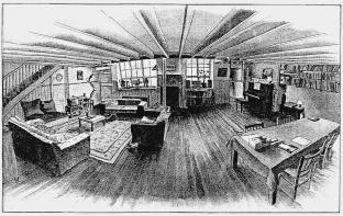
But, even the drawing of a room as
in Figure 6 is only relatively correct regarding the peculiarities of visual
perception. Actually, we perceive the objects placed in the room in “natural
perspective” [15] as showing in Figure 7. In the tonal drawing of a room, the artist has tried to represent the
objects seen out of the corner of his eye to left and right, in addition to the
space in front. The sofa (bottom left) is in reality parallel to the table
(bottom right). In certain types of perspective drawing, the back of the sofa
and the edge of the table, which are at right angles to the floorboards, would
be drawn along the same horizontal line. Here, they are at an angle to each
other because that is how you actually see them. Similarly, the central beam across
the ceiling is in reality straight and would be drawn so according to
conventional perspective, but when you look at it, it appears curved.
Figure
6.
Figure 7.
In addition to this, in many cases one-point perspective may give serious distortions. For instance, in “Fundamentals of Drawing” one can read that the cylinder is distorted because the vanishing point is too distant. The distortion happens because the shape has fallen out of a normal viewing plane and to see it you would need either to change the angle of vision or draw it in two-point perspective [16]. An example of this may be seen in Figure 8. The cylinder does not look “wrong”, but it is not convincing.
Figure 8.
3.
Pedagogy
How one can explain the inconsistencies of one-point perspective to students? Let us turn to the example of Figure 9 which is a drawing of the same cube in one-point perspective positioned at different distances from the viewer, but at the same distance from the horizon line. This example shows that the outer cube looks like a prism [17].
Figure 9.
Actually, it is the outer cube that resembles a prism and this is caused by the imperfection of one-point perspective. Descriptive geometry gives a clear answer to this question. In this drawing the horizon edges of the cube’s side plane are drawn longer than the vertical and horizon edges of the frontal side which are depicted in natural size. From the fundamentals of descriptive geometry we know that the segment of a receding straight line always will appear shorter than its actual length. The same example offers an explanation for the distortion of the cylinder (Figure 8).
Having studied from textbooks, which form the
students` basis of one-point perspective drawings in the case of a cube, the
students also draw the construction of polyhedral shapes with visibility side
planes incorrectly. Their conviction can be changed only by acquiring of
fundamentals of descriptive geometry.
4.
Defining the linear perspective
The general principles of perspective construction are reflected in one of the engravings by A.Direr (1525) picturing the peculiar device for the correct reproduction of perspective in drawing from the nature (Figure 10) created by the author. This engraving depicts the artist painting the picture and viewing the scene by one eye through the specific device with the hole and frame covered with the net of square knots. Frame with the net is positioned in a such length from the hole which allows a full view of the frame and figure without the turn of the head, e.g. without the transference of viewpoint. On the table in front of artist lays the sheet of paper also covered with the regular rectangular grid, which helps the artist to fill in the scene observed through the hole.
![]()
Figure
10.
Engraving by Direr illustrates the perspective
construction process on the two dimensional translucent picture as it was
interpretated by the artists of Renaissance. Contemporary theory of perspective
describes this process the same way. This theory suggests the common and fixed
viewpoint and translucent plane of picture to view the space behind the
picture.
Figure 11.
Figure
11 depicts the popular construction of cube perspective with its observable
apexes marked by letters ABCEKLM. Cube is positioned on the ground
plane (P1) frontally towards the picture plane
(P2). Picture plane is perpendicular in regard to the ground plane and the
projection of picture plane on the ground plane is the ground of picture
plane (X).
Line set at 90 degrees from the viewpoint
of observer (S) to the picture plane determines the central
vanishing point (S2), but line set at 90
degrees toward the ground plane – the station point (S1). The horizon line (h2), which intersects the central
vanishing point and represents the eyes level is located on the picture plane.
Looks of artist to the separate apexes of cube are connected with the straight
lines usually called the visual rays. Perspectives of cube’s
apexes are situated in points where these rays intersect the picture plane.
Projection of cube is created by the connection of perspective points of all
apexes of cube.
Similarity of perspective depiction to our
visual impressions is the main quality of these reproductions, which provides
the opportunity of truthful reflection of different objects.
Some regularities of perspective can be
deducted from the construction of cube’s perspective. Further will follow some
well-known information, however, the emphasis on this knowledge is necessary if
we want to reach the aim of this article.
5.
Main laws of linear perspective
Many
textbooks on drawing and perspective interpret these laws differently, though,
the meaning of these laws stays the same:
- Perspectives of all lines perpendicular in regard to the picture
plane will converge at the central vanishing point on the horizon line. Figure 11 represents the
perspective where the edges AE and BC,
perpendicular in regard to the picture plane really converge at the
central vanishing point [18].
- All horizontal straight lines, parallel to the picture plane (i.e. ground of picture plane X)
do not have vanishing points and their perspectives remain
parallel and horizontal lines. In the case of cube – these are edges
CE, BA and LK [19].
- Straight lines, parallel to the picture plane but not to the ground
of picture plane also do not have vanishing point (they are located in infinity)
and their perspectives remain parallel to these lines. In
Figure 11 these are the diagonals of the front edge AK and EL
[ 20].
- All the vertical lines parallel to the picture plane do not have
vanishing point and their perspective remain verticals (edges of cube BL,
AK and EM) [21].
Besides that, we have to mention that second,
third and forth laws can be combined in one definition: perspectives of
all interparallel lines parallel to the picture plane remain the parallel.
In space horizontal straight lines can be
located at any angle to the picture plane: all the horizontal parallel straight
lines located at acute angle to the picture plane converge at the vanishing
point on the horizon line (Figure 12) [22]. This law
determines the construction of cube projection in position where the observer
can see two side planes of cube and in this case the perspective of cube have
to be constructed with two vanishing points. However, if these straight lines
are set at 45 degrees to the picture plane (in Figure 11 these
are diagonals AC and BE), then the vanishing points
of these lines will be distant points D2 and D′2 which will be located in such a
distance from the central vanishing point which is equivalent to the distance
between the viewer and picture plane.
There
are lines which receding away from the viewer either descend or ascend. In descriptive
geometry these lines are called the general straight lines. They
are not parallel or perpendicular neither to the picture nor to the ground
plane (in Figure 11 these are the diagonals AM and KE).
General straight lines intersect the picture plane adequately above or
below the horizon line. Figure 12 illustrates the example of parallel
general straight lines ascending away from the viewer.
Figure 12.
These laws of perspective construction of straight lines allow to construct every complicated shape in perspective. Though, the deeper analysis of some of these laws asks for the more valid interpretation.
6.
The main problem of perception of perspective
Let’s have a more detalized analysis of concept
of perspective construction for the vertical straight lines, which contradict,
with the three-point perspective construction where the parallel vertical
straight lines converge in one vanishing point located above or below the
horizon line.
In textbooks this method usually is
illustrated by examples of many-storeyed building perspective construction. To
find the solution for the stated problem let’s focus on the axonometric
projection of model of many–storeyed building perspective constriction (Figure
13). The picture shows that vertical straight lines will remain vertical does
not matter how far we extend them, which rises the doubts and many questions.
Figure 13.
Many textbooks either ignore the
mentioned controversy or give a very superficial explanations about the changes
in slope of picture plane without any empirical prove of statements (“Three-point
projection for plans and elevation is more complex than that for one- or
two-point perspective. It can involve the incorporation of an inclined picture
plane set at the correct angle to the ground plane. Some methods require a
special plane of the object as seen from the inclined angle. This is prepared
by projection from a tilted elevation” [23]).
The essence of problem is that
neither in case with the description of laws of perspective construction, nor
in explanation of three-point perspective not all of the authors emphasize the
significance of location of object toward the field (or cone) of vision.
7. The cone of vision
It is well known that if one
carefully observes the shape and range of space seen by two eyes, one can reach
the less space above than below the horizon. Research proves that the angles
made by visual rays intersecting the horizontal line are approximately 45
degrees above and 65 degrees below. [24] Reach of space by the
visual rays to the right and left side is determined by the angle approximately
140 degrees (70 degrees to the each side).
Picturing the curved line drawn
through the four points ABCD and stationed on two perpendicular
axis we can get the rough shape of cone of vision (Figure 14).
Figure 14.
It is easy to test the fact that we have perfectly clear view of just those objects, which are positioned in a small sector in the centre of cone of vision. Approaching the edge of cone of vision there is a sharp decrease in clearness of visual impression.
The fields of best view A′B′C′E′ can be determined in vertical plane at angle 28 degrees but in horizontal plane – at angle 37 degrees (Figure 15). This means that to draw the standing person one has to move away from him/her not less than two of his/her heights. Only in these circumstances it is possible to perceive the whole person from one fixed point of view. From the closer distance we will be able to examine the figure of person only part by part. The same is correct also for the drawings of other objects.
Figure 15.
8.
Perspective of vertical straight lines
Figure 13 illustrating the axonometric projection of perspective construction of many–storeyed building proves that all the vertical lines in perspective remain vertical. But if you examine this figure from the position of cone of vision of views, to see the upper storeys the viewer has to rise the head and therefore to change the station point. In this case the main visual ray looses it’s perpendicularity in regard to the picture plane.
Let’s analyse this example from different aspect. For these purposes we have to spread out the picture in the position where the picture and ground plane will occupy the projective position (Figure 16). It is clear, that even in this position nothing will change and perspective projections of vertical edges of building congruent with the projection of picture plane will remain parallel.
Now, let’s mark the upper limits of cone of vision in picture upwards at angle 45 degrees, downwards – 65 degrees (Figure 15). Becomes clear that viewer will examine the building part by part. Point A determines the maximal limits of upper edge of cone of vision. Until the point A perspectives of vertical edges of buildings really will appear to be the parallel vertical straight lines.
To see the part of building located higher than point A we need to change the angle of vision, i.e., to rise the head. At the same time the central visual ray also will move above the horizon line. According to the law of perspective construction which states that central visual ray has to be perpendicular to the picture plane, let’s move the picture plane accordingly, for example, at the angle of 45 degrees in position P′2. In this case regularity about general straight lines (Figure 12) can be used. It states that these lines ascending from viewer in perspective will have the common vanishing point. To make this clear, let’s spread out also the Figure 12 to the position where the picture and ground planes will become also the projective planes (Figure 17). Comparison of this Figure with the Figure 16, especially the part of moved plane P′2, reveals the congruence of both pictures.
Figure 16.
Figure 17.
Therefore the line segments A - 4 and A′- 4′, defining the part of building edges positioned in regard to the new picture plane P′2 will appear the general straight lines, and their perspectives will have the common vanishing point.
Summary
Thus, one-point perspective is possible drawings of three-dimensional object in position where side planes are not visible. [25]
Law
of perspective construction for vertical straight lines will be correct if
supplemented with the definition of object position toward the viewer, i.e. all
the vertical straight lines, perpendicular to the ground plane, in perspective
will appear vertical only in cone of vision of viewer, beyond the reach of cone
of vision their perspectives will start to converge.
This conclusion is correct also for all the horizontal straight lines parallel to the picture plane and the prove of this is analogical the one for vertical straight lines. The peculiarity of this prove will be the move of central vision ray and, accordingly, the picture plane either to the right or to the left from the central vanishing point.
These example
allow to conclude that there is a need for correction of well-known
interpretations of regularities of perspective construction, namely: perspectives
of all interparallel straight lines which are also parallel to the picture
plane will not have the vanishing points only while located in the cone of
vision of viewer. Beyond the reach of cone of vision their perspectives will
start to converge and after all they will intersect the picture plane in the
vanishing point. The location of vanishing point will depend on the position of
these straight lines in regard to the ground plane. These lines can be
parallel, perpendicular or at sharp angle to the ground plane.
References
- Frolov, S.A., Pokrovskaja, M.V. [1985]. Searching for the Beginning. Stories about Descriptive Geometry . Moscow: Visshaja Shkola, p. 45.
- Slahova, A. Problems in the Perception of Perspective in Drawing – The international Journal of Art & Design Education. –
Printed and bound by The Alden Press, Oxford, JADE 19.1, NSEAD 2000,
p.102-109.
- Volkow, I.P. [1993]. Art Studio at School. Teacher`s book. Moscow: Prosveschenie, p. 59.
- Powell, William F. [1989]. Perspective.
Walter Foster Publishing, p.9.
- Ibid. p.12.
- Ozolinsh, M.
[1979]. Perspective and Theory of Shadows. Riga: Zvaigzne, p.39; Simane, Z. [1998]. Visual Art.
Teachers Book. Riga: Lielvards, p.26; Johanson, B.V., Klinduhov, N.N.,
Molovickaja, L.I. [1986]. School of Fine Art. 1 part, Issue
№1. Moscow: Izobraziteljnoe iskusstvo, p.103; Full course
of Painting and Drawing. Fundamentals of drawing [1994]. Parramon
Ediciones, S.A., p.50; Drawing [1975]. Ed. Serov, A.M.
Moscow: Prosveschenie, p.110; Bowen, Ron [1995]. Drawing
masterclass. The slade school of fine art. London: Leopard, p.144;
Stanyer, Peter & Rosenberg, Terry [1996]. Drawing systems.
Arcturus. Printed in Great Britian, p.23; Watson, Ernest W. & Watson,
Aidren. The Watson Drawing Book. [1962]. Bell Publishing Company,
Inc. New York, p. 32; and Metzger, Phil [1991]. Perspective Without
Pain, Volume 1/Part 1. Benedikt Taschen Verlag Berlin GmbH, p.7.
- Johanson, B.V., Klinduhov, N.N., Molovickaja, L.I. [1986]. School of Fine Art. 1 part, Issue №1. Moscow: Izobraziteljnoe iskusstvo, p.101.
- Stanyer, Peter & Rosenberg, Terry
[1996]. Drawing systems. Arcturus. Printed in Great Britian, p.23.
- Schipanov, A. [1970]. For Artists – amateurs. Moscow: Sovetskij hudoznik, p. 9.
- Arnheim, R. [1974]. Art and Visual Perception (transl. from English). Moscow: Progress, p. 269.
- Powell, William F. [1989], op.
cit, p.14.
- Arnheim, R. [1994] New Essays in Psychology of Art (transl. from English). Moscow: Prometey, p. 185.
- Powell, William F. [1989], op.
cit, p.15.
- Powell, William F. [1989], op.
cit, p.13.
- Smith, Ray [1995]. An Introduction
to Perspective. In Association with the Royal Academy of Arts.Dorling
Kindersley Limited, London, p.13.
- Full course of Painting and Drawing. Fundamentals of drawing [1994]. Parramon Ediciones, S.A., p.48.
- Nesterenko,
O.I. [1994]. Short Encyclopedia of Design. Moscow: Molodaja
Gvardia, p.43.
- Ozolins, M. [1998]. Perspective and Theory of Shadows. Riga: Zvaigzne, p.38.
- Ibid.
p.35.
- Ibid.
p.38.
- Ibid.
p.38.
- Ibid.
p.35.
- Smith, Ray [1995]. An Introduction
to Perspective. In Association with the Royal Academy of Arts.Dorling
Kindersley Limited, London, p.40.
- Barishnikov, A. [1955]. Perspective. Moskow: Iskusstvo, p.16.
- Slahova, A. [2000]. Descriptive Geometry in Drawing. Part.5. Perception of Perspective – DPU, Daugavpils: Saule, p.1-35.