Integration of 3D Simulated Set And Background Design To Create
Effective Photorealistic 3D Rendering
For Film & Animation
Faculty of Creative Multimedia, Multimedia University, 63100 Cyberjaya,
Malaysia
Email : sjjong@mmu.edu.my, eu_hui@hotmail.com
Abstract
This paper is to study on
the usage of 3D simulated background with life footage shot on film. To achieve
this, the look of the 3D background needs to achieve a certain stage of realism.
This will depend primary on the material and renderer applied by the 3D
application. Despite having the realistic look, the other aspect to consider
for a perfect merge requires one to skillfully match the perspective and
lighting. Besides that, the paper also elaborates on the difficulties and
suggested solution methods to be implemented. There is also an experiment
conducted to test the viability of the process. The results will show the
effectiveness of the merge implementation.
Key Words: 3D, film, set and background design, integrate, photorealistic
1.
INTRODUCTION
1.1An Overview Of 3D Realism
Photorealistic 3D rendering cannot totally rely on its
technical aspect only. Understanding of design principles and detail
observation on the surface attributes are two major aspects. One such principle
to consider is Cinematography. This is because the purpose of the 3D elements
created and embedded into the scene is primarily to enhance the storytelling.
Since there are times when one requires working on a very huge 3D models
database, the better solution to acquire a sufficient performance is to decide
on certain aspects that will define the importance of the workflow. Knowing the
strength and weaknesses of the 3D application can benefit the user to
anticipate what to expect for the final output. Besides that, it is also an
advantage to bypass certain technical problem that will most likely suffice.
Utilizing 3D application alone is insufficient to
fully do the job. The production process involves many stages before and after
manipulating the 3D elements on screen. One needs to understand the process
from digitizing the film, controlling the colour channels and bit rates to
preparing the necessary measurements to aid the 3D placement on virtual space
later on. Besides that, after the 3D scene is prepared for render, there will
be process of combining all the rendered layers and the footage back to 1
layer. Only then can the process is considered complete.
2. CONTENT
2.1Definition of
Set and Background Design
This indicates the designing of a location or
environment that establishes the timeline in which the characters will act. The
characteristics of set and background design are also to create and establish
the mood, atmosphere, time, place etc. In other words, this is the key element
to misc-en-scene. Mise-en-scene designates filmed event — set design, lighting
and the movement of the actors, mise-en-shot. In this sense, mise-en-scene
refers to a stage of film production that exists prior to filming. In this narrow
definition, we can clearly distinguish the filmed events from the way they are
filmed. The process of filming, of translating mise-en-scene into film, is
called mise-en-shot. A major part of the art of film making involves the
interaction between the filmed events (mise-en-scene) and the way they are
filmed (mise-en-shot). To make a successful film, film makers need to establish
a productive relation between mise-en-scene and mise-en-shot.
2.2Understanding
What to Expect on Screen
Graphics can be contained in two types of mediums:
Analog and Digital. Both carries different colour information. Although it is
easy to convert from analog to digital, vice-versa, the outcome of the
conversion won’t display the exact colour details. All this depends on the formats
and compressions that register the graphics bit rate. With today’s technology,
it is quite easy to achieve a proper colour balance for the conversion using
most softwares available.
2.3Logarithmic
versus Linear Colour Space
Some establish companies such as Kodak labs introduced the
mentioned software solutions to define how digital films would be recorded.
Thus, they came up with a format called 'Cineon' in which the brightness of the
R, G, B layers was represented as film density. The negative density of 2.048D above Dmin was recorded into a
10-bit space with values from 0-1023 representing the usable contrast range of
the negative film. Unfortunately for
computer users, the monitors displayed brightness with linear values generally
from 0-255 for each channel. So when one displays a cineon file format on
screen, the colours will look very desaturated or washed out.
However
most image processing operations expect a space that is mathematically linear.
Hence most people convert logarithmic cineon frames to linearised images whilst
working on them, only converting back at the end. There are many different ways to linearise an image depending on
your needs. One such way is to use a vectorscope. Of course there are other
reliable softwares that actually suffice for a proper conversion, but some
operators still prefer to judge by eye.
Fig. 1: Using Nothing Real: Shake software to work on cineon files.
2.4 Using a Vectorscope
In order to faithfully
digitize or reproduce video, postproduction and duplication facilities use
hardware devices called waveform monitors and vectorscopes.
Similarly, you can use softwares to accurately evaluate video levels specifically: color and
brightness. These instruments not only help one output a video program that
meets broadcast standards but also assist you in making adjustments based on
aesthetic considerations, such as color corrections.
A waveform monitor is
useful in measuring the brightness, or luminance component, of a video
signal. The waveform monitor works something like a graph. The horizontal axis
of the monitor corresponds to the video image. Vertically, the waveform
measures luminance, in units called IRE (named for the Institute of
Radio Engineers). Bright objects produce a waveform pattern (bright green
areas) near the top of the graph; darker objects produce a waveform toward the
bottom. For NTSC video in the United States, luminance levels should range from
7.5 to 100 IRE. Japan's implementation of NTSC standards permits a luminance
range from 0 to 100 IRE.
A
vectorscope measures the chrominance, or color components, of a video
signal, including hue and saturation. A vectorscope maps a
video's color information onto a circular chart. Saturation is measured from
the center of the chart outward. Saturated, vivid colors produce a pattern some
distance from the center of the chart, while a black-and-white image produces
only a dot at the center of the chart. The particular color, or hue, of the
image determines the angle of the pattern. Small boxes indicate where fully
saturated magenta, blue, cyan, green, yellow, and red (present in a color bars
test pattern) should appear. In NTSC video, chrominance levels should never
exceed these target areas.
Fig. 2: Using a reference monitor
to aid in color correction in Adobe Premiere
Pro.
3. Photorealistic 3D Renderings
Photorealistic rendering has played an important role
in creating compelling 3D renderings; this includes still image renderings and
animation. The definition of photorealistic rendering refers to construction of
computer images that in addition to geometry accurately simulate the physics of
materials and light, [1]. Supported by several existing researches and
invention in 3D rendering field, more techniques and approaches have been
introduced. Motivated by this, we have experimented with another method to
simulate photorealistic-rendering solutions. The method discussed here is mimic
realistic rendering effect, or a similar simulated result.
Most 3D modelers, artists, and
animators have a rough idea what rendering engines are supposed to do. A
rendering engine takes a 3D scene or model, runs through some obscure
mathematics to calculate how it's supposed to look, then creates an image. We briefly define the rendering process is a
process that translate 3D geometry into final flat image or animation file by
considering data from surface shading and lighting condition. This is done with
a mathematical formulation.
3.1 Utilizing Shaders to Achieve Realistic Renders
In the earliest rendering
systems, the only way to increase the apparent complexity of a mesh was to add
more polygons. This mean that the subdivision of the object needs to be
increased tremendously, thus slowing down the graphics memory. The more complex
the scene is, the slower the computer system becomes. If the subdivisions are
insufficient, the closer the camera gets to the object, the flat shading model
will tend to be more obvious, giving a more jagged look. This phenomenon is
also known as faceted. This is because the shading model would find the vector,
which was normal in relation to a face and use that information to shade all of
the pixels.
This all changed when Henry Gouraud developed his now famous, widely utilized,
and aptly named, Gouraud shading model. Gouraud works by finding the normal
vector pertaining to each vertex of a face, calculating the pixel color at the
vertex and then linearly interpolating that color across the face. This results
with a fairly smooth surface that takes only a modestly larger amount of
processing power than the flat shading model. The only aesthetically
displeasing aspects of Gouraud are the edges still appear faceted, as well as
the fact that the surface displays a star shaped highlight due to the linear
nature of the interpolation.
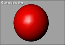
Fig. 3: Material using Gouraud Shading Group
A researcher by the name of
Phong Bui-Tuong expanded on Henry Gouraud's shading model by taking the next
logical step. Instead of finding the normal vectors at just the vertices, the
Phong shader calculates a normal at each pixel. By interpolating across the
surface based on the normals, Phong results in an extremely smooth surface with
accurate highlights the main drawback that Phong is requires a long time to
render. If one compares the Phong model against Gouraud model on two identical
pieces of geometry, one will see that it takes up to about eight to ten times
as long to render the model using the Phong shader. [2].
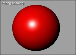
Fig. 4: Material using Gouraud Shading Group
3.2 The Qualities
of the Rendering Engine to Produce Realistic Results
Basically, a renderer serves as an ‘engine’ to convert the
3D dynamic graphics calculation to produce bitmaps. Since all renderers for
different 3D application or even standalone renderers are different one way or
another, the rendering time and the quality of the render differ. Some
renderers may specialize in a certain task but lose out on another aspect. It
is still subjective to say which renderer works best with all the 3D
applications.
Common features for these renderers that suffice to produce photorealistic
outputs have include ray tracing, caustics, global illumination, radiosity and
HDRI. The paper will elaborate on some of these features to a certain extent.
3.2.1 Caustics
Ray Tracing is a global
illumination based rendering method. It traces rays of light from the eye back
through the image plane into the scene. Then the rays are tested against all
objects in the scene to determine if they intersect any objects. If the ray
misses all objects, then that pixel is shaded the background colour. Ray
tracing handles shadows, multiple specular reflections, and texture mapping in
a very easy straight-forward manner.” Ray Tracing is very related with the
effects needed to generate realistic images; this includes accurate shadow
casting, surface reflections such as mirror, transparency objects,
inter-reflections, complex illumination models and realistic materials.
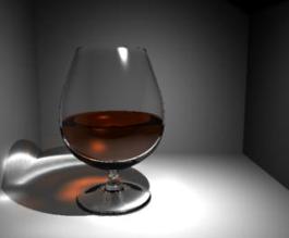
Fig. 5: Render using Mental Ray Renderer with Ray Tracing and Caustics
1.2.2
Radiosity
Radiosity
is a subset of global illumination approach, which commonly used for realistic
image generation. Radiosity approach has a strong relation with the theory of
heat transfer. Birn [3] explains, “Radiosity is an approach to rendering
indirect light, in which light is transmitted between surfaces by diffuse
reflection of their surface colour.” In another words, radiosity is the
indirect light that is distributed between objects. It is also view independent
rendering method. To make it clear, Cohen et. al [4] explains, “..the form
factor computation is approximately an order of magnitude greater than both
stages of solving the set of equations and rendering a view. The more important
loop is the one that changes the view point. Here there is no need to recompute
a solution and the same radiosity date is used to calculate any new view. “
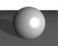 Fig. 6:
Rendering using normal Software Renderer
Fig. 6:
Rendering using normal Software Renderer  Fig. 7:
Rendering using Mental Ray Renderer
Fig. 7:
Rendering using Mental Ray Renderer
Fig. 8: Rendering using Global Illumination with Radiosity
4.Enhancing Photo-realism with Cinematography
According to Watkins (2000) [5], a basic element of
film often overlooked in 3D is composition.
Those who have worked in more static areas of art, such as photography,
drawing, painting, or sculpture, understand the importance of placing key
elements correctly. The same rules
apply to 3D: Sequences must be composed carefully, particularly if they contain
moving elements.
 Fig. 9:
Original footage shot on film
Fig. 9:
Original footage shot on film 
Fig. 10: 3D Wire-frame
Meshes are constructed and composited
Fig. 11: Final Realistic 3D Renders
Composited with the Life Footage
The first unit of
composition is shot size. The size of
the image within the overall frame (sometimes called image size) helps the
viewer get an idea of scope, scale, and importance. The film industry usually recognizes three or four shot sizes
that are also in 3D: extreme long shot (ELS), long shot (LS), medium shot (MS),
and close-up (CU). Each shot has a
definite purpose and communicates different things to the audience. Watkins
(2000) [6]

Fig. 12, 13: The images show that the impact of the scene can be
magnified using 3D
Fig. 14: The realistic look gives a convincing feeling that
the actors and ships are really there
To identify the camera
techniques in animation, for instance, it is specifically a fighting-scene.
Tong (2000) [7] says, “The HK martial arts movie are the best you can get. It
captures the essence of every fighting move and brings out dramatic scenes.”
Back in CG production, a lot of action sequences in CG movies or film are often
dramatized by motion blurs and atmospheric environment (dark, gloomy, rainy,
etc.) In this way, they can hide many imperfections and reduces work.
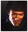
Fig. 15, 16: Reference 3D Images taken from
CG World Magazine
4.1 Perspective and 3D Cinematography
‘Perspective is the rein and rudder of painting.’ -LEONARDO DA VINCI
As
what Leonardo Da Vinci’s quote says “Perspective is something we usually take
for granted, but it was not until the early Renaissance in the fifteenth
century that perspective was discovered in Florence.” Its subsequent
application has had a profound effect on Western art. This supports the
statement that perspective is the single most important consideration in
creating believable composites and is of supreme importance in all aspects of
visual effect cinematography. It is
also the most common error. Perisic (1999) [8]
Elkins
(1997) [9] further explains that photography and cinematography are natural
extensions of the art of painting. In a
painting, the picture surface is a window through which the subject painted can
be seen; the cinema screen is a window through which a live scene can be
seen. In both cases, 3D reality is
‘translated’ into a 2D representation of that reality. This is accomplished with the use of
perspective.
True
linear perspective is based on the way the eye sees. Linear perspective is two-dimensional; it is based on the fixed
viewpoint of one eye. However, natural
vision is based on the viewpoint of two eyes, that is, it is
three-dimensional. Consequently, an
understanding of linear perspective is even more necessary in 3D
cinematography. Perisic (1999) [10]
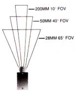
Fig. 17: This Image shows the basic
conversion from millimeter to degrees.
This
is subject to change based on the architecture of the 3D softwares.
Fig.
18: This shows the perspective distortion for the camera lens. This is because
the
surface of the lens is not flat, thus
distorting the width of the image.
4.2 Lighting
and Color Temperature
Perisic (1999) [11] says, “If perspective is the mother, the
lighting is the father of a good visual FX composite.” The two work hand in
glove to create the illusion of reality.
It is often the lighting of a studio set representing an exterior scene
that gives it away as unreal, particularly when it is composited with a real
exterior element.
He
further explains that the most obvious mismatches occur in the direction of the
key light, which in a typical exterior setting is meant to emulate the
sun. It shows up in the direction and
density of the shadows. When composting
two or more elements photographed at very different locations or studios, it is
often possible to overlook the obvious – the shadows. Yet, the shadows are of crucial importance to the composite
picture if it is to look convincing. A
mismatch in the direction and density of the shadows destroys the illusion even
if the perspective is matched perfectly, making the composite picture appear as
a collage. Elkins (1998) [12]
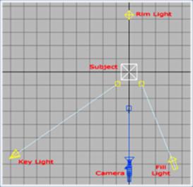
Fig. 19: Basic 3-Point Lighting Setup
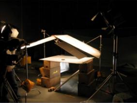
Fig. 20: With Reference to the 3-Point Lighting
Method, Additional Deflectors is used
to Bounce Secondary Lighting to Achieve Softer Shadows
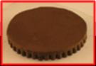
Fig. 21: Final Output of Lighted Object
4.3
The Technicalities Behind Lens Distortions
In the whole world, all camera lens created have a slight
curvature to it, no matter weather it is man-made or machine made. The only
flat lens that exists is the 3D camera lens. Due to the different architecture
for different 3D applications, there can be no direct calculation to convert
the information from live footage to 3D. This will result having difficulties
matching the constructed 3D model to the life footage model.
Fig. 22, 23: The Images Above Shows the
Effects of Perspective Distortions
for Real Camera Lens in Comparison to 3D
Camera Lens
One other main factor that makes this process difficult is
because the focal point for the camera is never lock down on its position in
space. The focal point is the position on contact with the film whereby light
is focusing on. The distance between the focal point and the lens is the focal
length. Digital zoom in most cameras will cause the focal point to adjust its
position along the floating path. There is no exact calculation to know where
is this ‘virtual’ position of the focal point. Furthermore with the lens
distortion, the only way to judge for a perfect match for 3D is by eye.
5.Conclusion
The review of this paper clearly shows the advantages of
using 3D as a tool to subject as photorealistic graphical elements to enhance
the mood and the theme to better tell the story. It seems to be a cheaper yet
safer solution to achieve the realism quality compared to certain other
mediums. Even so, if there is a need to achieve another level of realism, 3D
shows potential for a bright promising future. Only time can tell.
It
is a long shot to believe that 3D might not be the limit anymore in terms of
design. Space as we know it now, reside in 3D. The future development of the evolution
of 3D might take us through the exploration of greater depths, thus unlocking
the secrets bringing us 4D, the fourth dimension. It will be possible that the
manipulation of space in 4D will breath a new meaning of the wonders of what we
can produce.
6.REFERENCE
Malhotra
Priya: 2002, Issues involved in Real-Time Rendering of Virtual Environments,
Master of Science in Architecture Thesis, College of Architecture and Urban
Studies Blacksburg, Virginia.
Starts Your Engine: A rendering Primer
url: http://www.3dgate.com/techniques/000424/renderpipe
J.
Birn, Digital Lighting and Rendering, New Riders Publishing, Indianapolis. 2000
Cohen,
M.F. and Greenberg, D.P., A Radiosity Solution for Complex Environment, In Proceedings
of Computer Graphics. Siggraph 85, 19(3), 31-40. 1985.
Watkins, Adam (2000). Visual Storytelling Through Film
Techniques. Oxford: Focal Press, Pg.30
Watkins, Adam (2000). Visual Storytelling Through Film
Techniques. Oxford: Focal Press, Pg.31
Tong,
F (agentfrank@hotmail.com). (2000, July 30). Interviews. E-mail to June Jong
(jannejune@usa.net). [ 26th August 2000]
Perisic, Zoran (1999). Visual Effects
Cinematography. Oxford: Focal Press, Pg 62
Elkins, Elkins,
David W. (1994). Motion Picture Camera and Lighting Equipment. Oxford:
Focal Press, Pg.36
Perisics, Zoran (1999). Visual Effects
Cinematography. Oxford: Focal Press, Pg 72
Perisic, Zoran (1999). Visual Effects
Cinematography. Oxford: Focal Press, Pg 75
Elkins, Elkins, David W. (1994). Motion
Picture Camera and Lighting Equipment. Oxford: Focal Press, Pg.59