Generative
Layout for A Small Building
Dr. Tomás García-Salgado
BArch, MSArch, PhD, UNAM
prize, SNI nIII
Faculty of Architecture,
Autonomous National University of México.
e-mail: tgsalgado@perspectivegeometry.com
Abstract
Among the classical principles in
architecture the so-called of unity
was popular and widely spread across the world. “The correspondence of the whole to the several parts, of the parts with
regards to each other, and of these again to the whole”, was the beauty’s
formula of the form. Many immutable
classical buildings withstand this principle. The idea to endow a building with
flexible spatial organization appears
in 1904. Several decades later, at the end of the 1960’s, the design method
theories emerge centering their aim on the design
process. Beauty was not any longer playing the central role on stage. It
was time to solve unknown people’s needs under socio-economical bases by the
aid of geometric and mathematical operations to design. Nowadays generative design adds the idea of spatial transformations
within time in response to the daily economical and technological changes.
It seems to me that putting these
architectural trends at once could be a good idea. Beauty, flexibility and transformation
could be the major issues in design. I will try to explain here this idea
through a real example in architectural design. To begin I will describe the
problem’s background, thereafter how the building’s first image was rendered in
perspective. In the second part, a flexible spatial organization is introduced
by the so-called cellular analysis method in order to satisfy the
program requirements, and then the generative principle is applied to both the
spatial system and the urban layout to foresee the building’s future
transformations. Finally, when time comes about the first transformation we
will see how it was interpreted.
1.0
The Problem Background
The City Hall of Toluca (México) entrusted me with the design for a small public building in 1992. As donation they accepted a 17m x 34m urban lot, which really is a small piece of land. The mayor of the city asked me to consider the immediate needs but keeping in mind the building’s future growth.
Time was crucial to get a preliminary
architectural solution. I received the mayor’s phone call one day in the
morning requesting me to consider some drawings by the next day’s morning. The
only available data at the moment of the call were the measures of the lot and
the visual memory of the plot that I had visited the week before —when all
things were just a prospect. But sometimes politicians want, here and there,
things to run almost instantaneously.
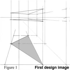
How could a generative-layout for a building within its site boundaries be proposed? This was the inevitable question related to both the present requirements and the future building growth —which the client asked me to foresee. Based on the fact that the lot proportions formed half of a square I asked to myself, why not develop the project as an entire square but build it as a half? This way the building could reach its final shape when the chance to acquire the neighbor lot became. Nevertheless the essential issue to deal with at this point was: how could I make obvious to others such idea of the square? And the simplest answer I got was: building up a triangle as a half of a square but making it obvious. In other words letting the building speak through them.
1.1 First Perspective Image
Having these questions in mind and no
time to waist I started modeling a geometric shape directly in perspective
straightaway—by means of the so-called Modular
Perspective method (the author’s)
since there is no need of any aid from other geometrical projections. [[1]]
The shape I was looking for must observe some restrictions such as leaving free
at minimum 25% of the total area. I choose a regular geometric shape but
opposed in orientation to those of the neighbor’s apartment houses, thus I laid
in perspective a triangular volume thoroughly fitting the rectangular shape of
the lot; see Figure 1. I was aware at this point, of course, of the inverse
design process I had chosen, pursuing first the building’s shape appearance and
the functionality of its inner spaces afterwards. It is quite reliable to
proceed this way if one knows how to make any given spatial organization
flexible.
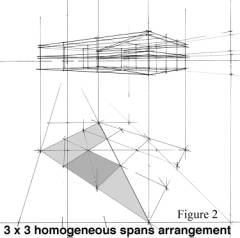
The initial area requested and assigned budget justify the two floors volume. Such calculation was easily determined applying the square-meter cost criteria. Having the triangular shape duplicated on the ground, I started to analyze the best modulation criteria to apply. Putting forth partitions 2 and 4 on one side of the triangular shape some inconvenient came up, being partition 3 the best to satisfy the structural modulation criteria for the plan. Hence the first space lattice was set for the vertical structural elements by means of a 3 x 3 homogeneous spans arrangement; see Figure 2. This array either fitted well a half of a square or in the future could complete it as well. At the core of the layout abided a triangular open space to let the sunlight in. This small space was covered with a transparent roof at the summit of the two stores to warm the building’s interior.
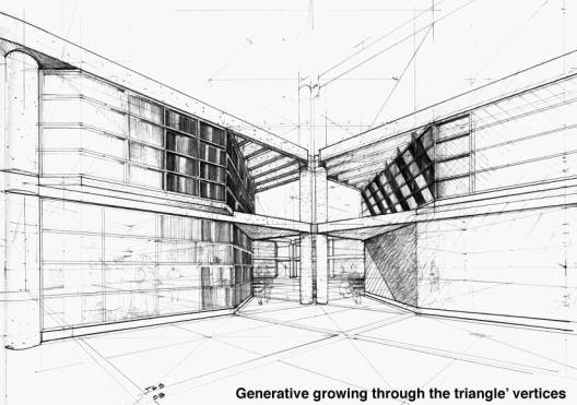
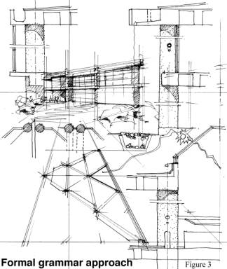
Once the general layout was set the main architectural elements were next to define. To build the structure I chose reinforced concrete instead of steel because the contractors were more familiar with it. Circular columns and flat slab floors conformed the basic building system, thereby the ensemble detail between these elements was important to analyze according to its position in plan, formal variations and proportions. Notice how the triangular geometry of the building within that of the rectangular lot generates five different constructive solutions for columns and floor junction. Sketching one by one within the same formal grammar allows us to easily approximate its solution, as it is show in Figure 3.
Of course this theoretical description
was not crossing my mind so orderly at the time I was working. We designers use
to work in a much more complex manner until we feel to get something that
matches the pursuing solution of the problem. It was rather merging all the
above-mentioned aspects during the perspective elaboration for the client.
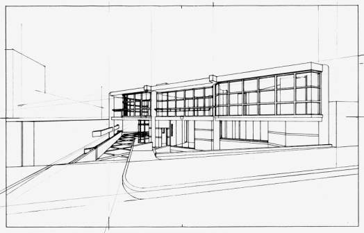
Unfortunately my original drawing was lost but resembles pretty much alike to
that of Figure 4.
2.0
Cellular Analysis
There is in architecture, as we know,
more than one solution for a given program, or shall we say, for a problem. But
the question is how to make suitable a “solution” in order to satisfy that
program. The features of a program in architecture are basically defined by the
users’ needs. Nevertheless the needs change throughout the time due many
factors mainly by those of growth and modus operandi. Any way a program must
take into account several guidelines, for instance, the available budget, a
specific demand about the structural system, special furnishing employed, and
so on until all of the client’s requests are compiled. As usual the architect
must check out the requirements list with the client in order to fulfill the
program. Although in my case this program was plain and simple the cellular analysis method was applied to
assure the spatial system flexibility.
Cellular
analysis is a
group of geometrical operations exerted to find out the possible spatial
arrangements of a cell within a spatial
system. The basic geometrical operations for a given spatial array are
permutations and symmetries. These operations can be systematically applied
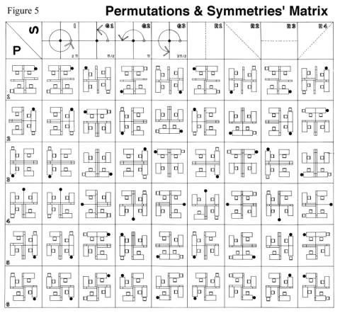
through a matrix, as it is exemplified in Figure 5 by the typical office
unit-work array. As we see, there are 48 different arrays, which is quite an
extensive number to analyze case by case. So the best strategy to follow is to
consider first the possible shape arrays
within the general layout system in order to simplify the matrix application.
It is important to be aware that the essential notion in cellular analysis is that of
“spatial array.”
2.1 Definitions
Before showing how cellular analysis was applied in our example, it is necessary to
introduce some definitions in order to clarify what the concept of spatial-array means:
Spatial array is the resulting operation of laying elements within a spatial cell.
Element is any material thing that
can be fixed or movable and belongs to one or more spatial arrays.
Function is a group of human
operations that can be attained directly or indirectly by means of an element.
Activity is a group of functions that
generates one spatial array.
Spatial system is a set of spatial
arrays that conforms a building.
The extension of the concept of element goes beyond to all kind of
furniture including many other parts of a building, such as windows, doors,
walls, columns, glass’ integral-facades, any sort of installations, equipments,
and so on. Depending on the elements’ ‘fixed’ or ‘movable’ condition the
spatial arrangement flexibility is determined through the geometrical
operations aforesaid. There are the following element restrictions within a
spatial array:
1 If a fixed element is
attached to a movable one this last turns to fixed.
2 If a movable element is next
to another movable, both are permutable to each other.
3 Equal elements are not
permutable.
4 Similar elements, not
attached to a fixed one, can permute.
Other aspects not mentioned here are: the
spatial array properties, the elements properties and restrictions, the
feasible relations among elements and, the feasible relations between the
spatial-array shapes and elements. It would be quite extensive to quote here all
the theoretical principles and definitions involved in cellular analysis, so I recommend —to those who want to know more
about it— to consult my book on the subject. [[2]]
2.2 Application
A building during its lifetime must be
adaptable for internal transformations, even for those that radically could
change its use. Of course the adaptability idea is not new, it began in 1904
with Perret’s free-plan for the apartments building in Rue Franklin 25 (Paris).
As in Perret’s design the scope of cellular
analysis is to handle a variety of spatial arrays pursuing the flexible
spatial-system behavior. In general terms its procedure is as follows:
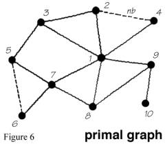
The first step is to translate the
requirements’ program into a primal graph
in which all the desirable spatial-cell relationships are established. As we
can see through Figure 6, all spatial cells, from 1 to 10, conform an
interconnected graph in which the dots represent areas or spatial cells and the
lines define the kind of connectivity between each of two of them, that is, if
they have connectivity or not.
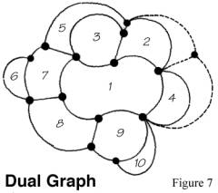
Now the second step is to translate the
primal graph into a dual graph, in
order to conform the areas of the spatial system, as it is shown in Figure 7.
The dual graph becomes a sort of areas’ elastic model since its boundaries
have no specific form. Now dots are transforming into areas keeping their
connectivity relationship. As it is noticed natural frontiers appeared. This
graph is a sort of topological architectural plan much easier to visualize than
the primal graph, allowing the designer to modify or add new boundaries.
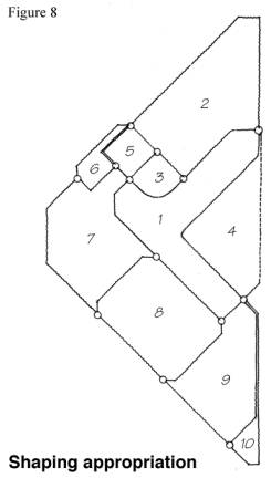
On the third step the topological
dual-graph appropriates the pre-established layout until its forms and
dimensions are concealed, as it is shown in Figure 8. When there is no
pre-established layout then it must be inferred. [[3]] This cellular mapping operation is
comparable in some way to that of packing items on a box or container pursuing
space economy, the only difference being that of the connectivity relationship.
It is exactly upon this relationship where complexity in architecture resides.
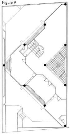
The rest of the design process depends on the architect’s abilities to develop
all the architectural features of the system; see Figure 9.
3.0 Generative Layout
The idea of a generative layout involves
mainly two concepts: growth —as in the building’s capability to increase in
size—, and transformation —as in the building’s capability of internal spatial
arrays variety. In our case, growth was foreseen by increasing the building up
to a third floor and then by duplicating it. Transformation was foreseen as the
inner quality of the spatial system to be tested throughout the time. These
concepts establish the original architectural grammar of the building, which
can be used towards new formal interpretations, as Palladio suggested in I Quattro Libri, otherwise hybrid
architecture will be the result.
“And although some of the designed are
not entirely finished, yet may one by what is done comprehend what the whole
will be when finished.” In this Palladio’s statement there is an enclosed generative-design idea. Looking closely
at the words “…by what is done…” they
implicitly involve the idea of a preestablished architectural grammar of his
works. Of course, this or any other generative concept is not explicitly
exposed in I Quattro Libri. But as we
know, all architectural elements in Palladio’s designs correspond to one
another mainly through the so-called symmetry and proportion rules. Thus, by
observing Palladio’s rules someone may be able to accomplish an unfinished
building of his as Escamozzi did it for the Villa Rotonda and Teatro Olympico.
The principle of unity was ruling
architectural design in Palladio’s time under the Vitruvian precepts of firmitatis (firmness), utilitatis (usefulness) and venustatis (beautifulness). [[4]]
By building in stone, classical and renaissance architects did not give to much
attention about transforming, besides it was not needed because architecture
was understood as a whole without any formal or
spatial changes to be made. But going back in time, to ancient Egypt, Imhotep
transformed the mastaba into a pyramid by reshaping its profile and increasing
its height at the same time. [[5]]
Egyptian architects design buildings for eternity but they did not realize they
were built without a future. The idea of transforming without destroying or
superimposing seems to belong to our time. It is a survival idea to avoid
building’s death by recycling them within the urban areas since architecture
cannot move, at least until today.
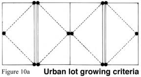
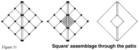
Thus, buildings and urban plots must be attached to each other under a generative layout capable of supporting transformations. My modest example —in scale— was settled in place as a primary layout capable of transforming according to the urban layout, as an invisible path to follow, to guide or suggest what is next. Figures 10a and 10b show us how the building can grow up along the street —up to four times— within its urban layout by using the right limit of the lot as a reflection axe.
The triangle’s assemblage through the
open patio will conform a square building, which theoretically would allow
increasing the initial area up to three times when the third floor is
completed, as it is illustrated in Figure 11.
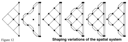
The main shaping variations of the
spatial system, based on the 3 x 3 homogeneous structural spans, were explored
in Figure 12. Whereas the inner spatial system layout shape is preserved it can be played in forms. That is, the
design of the form undertakes once
the spatial system has been solved. The material form through proportions
always withstands beauty.
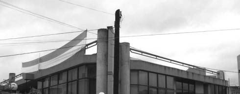
The expected generative code to be interpreted by another designer was the triangular central patio, but as half of a square in order to arrange the whole building around of it. Eight years later, when the City Hall administration acquired the neighbor lot, an architect —that I do not even know— completed the first square but misinterpreted the patio’s code. He only was able to read the exterior triangular shape of the building’s grammar, fairly enough, but missing the essential; see Figure 13 (Along two occasions I was unable to take a better photograph because there were buses occluding the frontal view). At the present I am certain of the exterior obvious code that impelled the designer’s approach but uncertain of its interior supposed signify.
Joining the squares’ vertices at the
reflection axe creates an interesting spatial variation. An important aspect I
had to deal with during the design process was to closely examine all the
spatial alternatives I had in mind, as the one illustrated in Figure 14.
The new City Hall administration called upon me this year —on September— requesting my advise of what to do in order to increase the construction area. As they already know a third floor can be added to the building I had designed, but the problem is that the new building floor’s level did not match in height with it. When we went to visit the building I discovered the reason the other architect had to misinterpret the patio’s code. He built an auditorium taking almost the total area of the lot leaving no room for the patio. Nevertheless this architect wanted to preserve the exterior triangular appearance, for aesthetic reasons, by giving the auditorium’s hall this form. It was a pity that of the lack of correspondence in height between the buildings’ floors the expected horizontal growth was annulled.
What was my advice to City Hall administration this time? Start over again in a new location considering a broad program of possible scenarios, and if possible to hire a dexterous architect or at least learned in Vitruvio’s principles.