Generating
architectural spatial configurations. Two approaches using Voronoi tessellations
and particle systems.
Paul Coates AA Dipl.
Christian Derix Msc Dipl Arch
University of East London School of Architecture & the Visual Arts
School\ of Architecture and the Visual Arts,
University of East London, London, United Kingdom.
Email p.s.coates@uel.ac.uk
c.derix@uel.ac.uk
Ing. Stefan Paul Krakhofer MSc
School of Architecture and the Visual arts,
University of East London, London, United Kingdom.
e-mail: krakarch@gmx.net
AbdulMajid Karanouh MSc
School of
Architecture and the Visual arts, University of East London, London, United
Kingdom.
Email: abdulmajeed_k@yahoo.co.uk
|
|
Abstract
It was one of the primary goals of the original Master’s programme in Computing and design at UEL in 1991 that we should work towards defining morphological generative processes for the conceptual design of architectural objects. These two papers offer a range of techniques which have been developed by two of this years MSc students (04-05) which show that we are getting close to this. The approaches range from computational geometric approaches (3d parametrics and voronoi diagrams) to emergent spatial orgaisation using agent based modelling. In many cases the resultant geometry is defined to the point where it can be transferred to advanced evaluation and fabrication systems, thus making this work sufficiently developed to begin to form a useful part in practical design processes.
Paper 1: Stefan Krackhofer Form evolution -
organised spatial distribution
based on CA and Voronoi information
In my
profession as an architect I aimed to develop a system, where space per se
actively communicates its needs and reactions to changes in its
environment. In contrast to many other professions and sciences; Architecture
also has to create complexity and space. As such, collecting and processing of
information becomes an important part of computable space in order to make and
support decisions and consequently to change, adapt or manipulate space.
The
implementation of a space-filling topological structure - the voronoi diagram -
simulated the natural information exchange of particles in the environment. The
voronoi approach subdivides the whole space into a set of sub-spaces according
to the distribution of the objects. Each vertex represents a voronoi-cell and
thus has its own Voronoi space which defines implicitly the spatial adjacency
with the adjacent objects. Within the Voronoi cell, contained locations are
closer to that object than to any other and thus creates a spatial
relationship. The adjacent relationships between the spatial objects are
reflected from the tessellation and are represented by the Delaunay
triangulation.
The
voronoi foam enables the collection of spatial information, the detecting of
spatial characteristics which can be classified and organised into coherent
pattern, as well as the manipulation of information and therefore space itself.
Supplied
with the Voronoi information a new generated system starts to perceive and
adapt and co-adapt itself to the environment according to its inherent nature
(tasks or rules).
1.2. Introduction
Our environment as
perceived is in a state of permanent flux, triggered by invisible forces of
nature and the natural laws of feedback and relationship. Science describes,
that naturally observed physical phenomena, from galaxies colliding with each
other to quarks jiggling around inside a proton, can be explained by
“fundamental interactions”, a mechanism by which particles interact with each
other. Observing this mechanism closer we have to add, that particles do not
directly interact with each other but rather generate a field, which affects
the behavior of distant objects. Information or knowledge is transmitted
through the medium of each particle’s individual field. The spatial environment
can thus be understood as a complex system structured by relationships between
particles. Consequently, we can note that the system’s manifestation as a
spatial configuration communicates its inherent knowledge as visible
information. Perceived space can thus be translated as a map of pattern of
complex relationships between particles.
1.3. Personal Space
In my experiments I
focused on the “field” and the data exchange within this medium. Exploring the
field - the sphere of influence around particles, which I rather term the
“personal-space” (PS), I derived a concept which is stated as follows: “Space
is made up of particles and their relationships. Interaction and communication
is made possible through their personal space and dependent on the neighbor
relationship, based on CA principles.”
The developed analytical
software tool generates a personal space around a vertex and detects its
neighboring vertices for interaction. I translated this concept into reality by
use of the computational geometries that are referred to as Voronoi diagrams
and its dual concept Delaunay triangulation. However, in order to reach an authentic
3D description of space, the structures had to be translated into 3D. Thus, the
Delaunay triangulation turned into a Delaunay tetrahedralisation and the
Voronoi into a 3D Voronoi-cell.
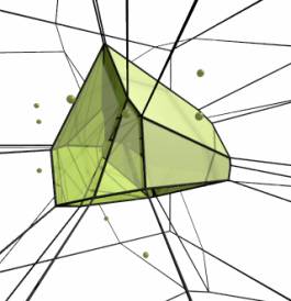

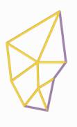
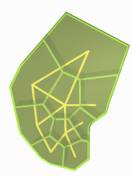
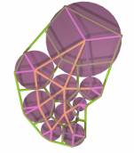
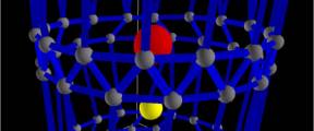
fig 1 3d
voronoi
1.4. Description of the Voronoi approach
The Voronoi diagram
generates a space-filling topological structure and is one of the most
fundamental and useful constructs defined by irregular lattices, emphasizing
its excellent applicability in modelling natural phenomena, the investigation
of their mathematical, in particular, geometrical, combinatorial, and
stochastic properties, and its computer-based constructability and
representation. The Voronoi approach subdivides the whole space into a set of
sub-spaces according to the distribution of the objects. Each vertex represents
the center of a Voronoi-cell and thus has its own Voronoi space which defines
implicitly the spatial adjacency with the adjacent objects (or the “influence
space” of the objects). Within the Voronoi-cell, contained locations are closer
to that object than to any other and thus create a spatial relationship.
1.5. Description of the Delaunay approach
The adjacent
relationships between the spatial objects are reflected in the tessellation and
are represented by the Delaunay triangulation, which maximizes the minimum
angle of all the angles of the triangles in the triangulation. The
triangulation of space defines the nearest neighbours of a vertex and generates
a topological network.
1.6. Coupling of Voronoi and Delaunay
In coupling both
approaches I generated a network of topological relationships such as
connectivity, minimal-adjacency and maximal-adjacency. Further, the grouping
and demarcation of equal or related entities can be conceived from the
Voronoi-diagram.
The Voronoi foam enables
the collection of spatial information, the localization of spatial
characteristics which can be classified and organized into coherent pattern, as
well as the manipulation of information and therefore space itself.
1.7. Application of the Voronoi foam
In the application, the
procedure is described as followed:
During the initial - the
preparation loop, all verity of the CAD–model are saved into “object” arrays
and receiving the name of the object as their ID, which they are belonging to.
The observation loop
generates the boundary condition for the system around the area which is
defined to be observed. The user defines the boundary by drawing a box on the
screen around the area of interest or the program chooses the edge of the
CAD-model as its boundary.
Now the algorithm can
start to compute the relationships by starting with the triangulation, followed
by the generation of the Voronoi foam. Each vertex has its own Voronoi space
and after checking the vertex ID, the vertices with the same ID are grouped
together to evolve the object’s personal space. By now each vertex can receive
information from their neighbors, since the system is based on CA principals.
The information can be position, distance, volume, color, whether it is
shadowed, temperature, ID, size of the whole object (bounding box), the amount
of neighbors the neighbor cell has and so on.
1.7.1 Way finding
The Voronoi foam was
than implemented as the background information into navigation, especially way
finding. In order to find the shortest way from object “A” to object “B”, all
boundary vertices of “A” ask their neighbours outside their personal space and
they ask their neighbours and so on till they find “B”. This search approach
evolves a network of interlinked tree-structures. The path between “A” and “B”
can than be drawn by following the branches of the network. By now the path is
“as the crow flies” and has to be corrected to the space in between the
objects.
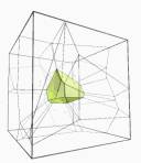
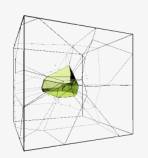
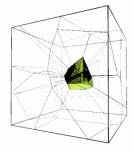
1.7.2. Occupation analyses
Another application for
the Voronoi foam is in the occupation analyses of space. In that case the
search agents are themselves the centre of Voronoi cells. During the search the
agents receive information of the surrounded cells. If the information such as
distance, brightness, height, …fits their inherent needs, the agent occupies
this position.
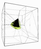
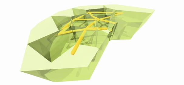
fig 2 3d
voronoi showing spatial organisation within a cube
1.7.3. Space evolution
The active process of
generating and evolving spatial forms demands the introduction of a process
which leads to equilibrium among all entities of a system, the theory of
self-organisation. In the context of architecture I find it more suitable to
refer to this process as co-adaptation (structural-coupling) among the parts
triggered by feedback.
“Form”, is the fixed
goal in architecture and thus the aim was to develop an algorithm which
generates “form” out of complex relationships among disorganised subsystems.
In order to apply a
method of organisation, subsystems or functions have to be defined and set in
dependency to each other and to general attractors. As such a clarification of
the term “function” has to be found.
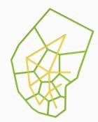
The Images below
describe the process of space evolution. Starting with a self-organisation of
functions followed by the application of the Voronoi foam.
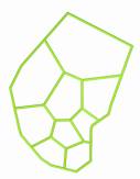
1.7.3.1. Feeling a pre - Image of Function
Function can generally described
as the accumulation of needs, however, if we were to define function
accurately, we have to consider that this demands knowledge of the occupants,
their needs and desires, consequently their feelings. In order to take human
feelings as the core motive for architecture we have to analyse human behaviour
in their environment or interview them in order to translate the results into
an algorithm which generates the pre-image of
function.
This would be
accompanied with a tremendous effort, yet, worthwhile since utilisation, size,
proportion, orientation, and neighbour-relationships could then be derived.
As such, an efficient
way of accumulating relevant data is to obtain the information from tradition,
building-regulations or in case of competitions, from the “raum-program”.
Deriving the functions
from the “raum-programm” was within the way I took. Starting with the
translation of the “raum-program” into an array subdivided into sub-systems and
organised according to their relationships. The sub-systems were then
substituted by autonomous intelligent agents who have knowledge of their
position in space, know who their nearest neighbour is, know who its aimed
neighbour should be and its preferred orientation.
1.7.3.2. Self – organisation and boundary condition
By now the system is
prepared and ready for the self-organising process to act on. Realising that we
do not have the possibility of parallel computing, I decided to start the
process, step by step, by increasing the fitness of one agent after another,
until the topological network is reached. Followed by activating external
attractors, such as feedback of the occupied space, sun, orientation and
shadowing, which led to unexpected chaotic phenomenon and finally to the
collapse of the system. It turned out, that the direct interconnection of
subsystems did not allow any adaptation, since this would simultaneously result
in the loss of fitness. In other words, the demarcation or boundary conditions
had to be rethought.
The nature of the
boundary between entities became a serious question. I observed that the highly
fluctuating dynamics of interacting subsystems were triggered by small changes
of their position, even when one subsystem was in equilibrium. This phenomenon
caused an imbalance of the whole system and resulted in a permanent
fluctuation, never (at least not for a very, very long time) reaching
equilibrium.
Struggling with this
problem I remembered how I started to design with paper and pencil (outside
under the sun, relaxed, free and independent), even with wobbly strokes it was
relatively easy to develop design. Or, do I now realize that the wobbly stroke
was exactly the cause for a good development? Musing on this fact, I realised
that the system demands a wobbly stroke. I came up with the concept of a
precise system encased within a viscous medium that allows for uncertainties.
If the optimal orientations of two functions in a precise system are
incongruous to one another, the positions of the other functions are
compromised as they are directly moved out of place by the local optimisation.
Whereas, in a viscous medium, the functions are able to move freely around the
centre of their axes without disturbing the adjacent functions, allowing for an
overall optimisation. Consequently, we have to pay special attention to the
medium as it assumes an active task and therefore requires a dimension; in
other words, an embodiment.
First I rejected the
idea that a system inside a system requires a system to exist, but I realised
that this is exactly the case. The boundary maintains the equilibrium of its
inherent systems even when the boundary’s environment is fluctuating because it
can absorb a certain amount of turbulences and stress.
Developing this idea of
absorbing and balancing further in an architectural-engineering context,
structural tasks can be assigned to the boundary-dimension. Considering that
all systems are nested and exchanging information, force visualised as
information can be trickled through the system so as not to irritate it but
arrives at its destination where it can be absorbed.
In all, my concept
illustrates the implementation of functional organisation with structural trajectories,
which are enclosed within the boundaries. It is obvious that another dimension
of feedback evolves within this constellation, which I would define as mutual
(co)adaptation. Before the subsystems reached equilibrium they already altered
the “form” of the whole system. The system feeds back the “new” information
about “external”-forces which needs to be carefully diverted through the
system. Continuing this process results in “general” equilibrium, or as I would
call it in the vocabulary of architecture: aesthetics, where beauty originates
from needs.
1.8. Conclusion
Generating
spatial effects enabled through simulating phenomena of space, material, light,
wind, sun, sound, or behaviour clarifies that architecture is increasingly
becoming a simulation rather than a representation of space.
The
study of architecture therefore has to consider simulation as a powerful
design-tool, in order to understand and implement complex relationships. The
educational nature of simulation shows itself when developed through the use of
algorithms in programming, altering the study of architecture. In carrying out
experiments and writing algorithms, I learnt that the ability to identify
pattern is fundamental to the design process. As such, the personal interaction
between student and algorithm supports an increase in the understanding and
knowledge about patterns, their relationships and compatibility. This process
trains one to work with pattern since experience can be gained from feedback,
whether visually or accoustically, triggered by the students’ decisions and
actions.
The
“system-view” of architecture which has the goal of designing a system rather
than a form will change the way we study and practice architecture; and will
likely lead to an increase of quality in architectural design.
In
order to facilitate this shift, designers should strive for a conscious
transfer of authorship. Following my experiments, my position evolve from the
role of dictating the behaviour of subsystems to the role of coordinating them
which can be illustrated by the following analogy: from an audience’s point of
view, the conductor dictates how the orchestra should play the music and is the
driving force behind the musical performance. From the musician’s point of view
however, the role of the conductor is not to dictate but to improve the whole
by coordinating creatively. He is merely piecing the entities together into a
harmonious whole. He is no longer the centre of the performance / design but
part of it.
As
such, the definition of architecture is becoming more complex than before, but
with the significant advancement that the architect is not the centre of
change, but an important conductor in the system. The system “architecture”
interpreted as a subsystem of our environment led to the research in nature. In
all, nature is an open system with inherent invisible laws of feedback and
relationships which strive for equilibrium. The tendency towards equilibrium is
manifested in the process of self-organisation. The result of this unique
process is form. Ultimately, nature knows best how to create form, not in the
sense of a random shape as we commonly perceive form to be, but as an
equilibrium between entities. If we are to be as good of a designer as nature
is, we must find a way to successfully implement the process of
self-organisation into architectural practice. The results of my experiments of
self-organisation showed a promising first step in its applicability in
architecture. Although the algorithms did not perfectly organise the entities,
the final form was a satisfactory compromise.
We
must realise that natural design is merely “good enough” to fulfil specific
tasks in relation to its environmental system. It is barely optimised for these
specific tasks, forever a good compromise between all entities in a whole.
I
was able to exploit a sliver of the playground of biological evolutionary
systems, yet there is so much still to be uncovered in Mendel’s garden of
architecture.
Paper 2: AbdulMajid Karanouh Architecture, Agents, &
Hyper-Surfaces:
High-Tech Building Envelope Generative Design
2.1 introduction
We
have always admired and observed how natural systems are generated in nature
and how different intelligent technologies and behaviours emerge during the
generative process and how superior those technologies are to the ones we use
to generate and construct our own designs and systems. We understand that all
elements of any system found in nature, whether ‘live’ or ‘dead’ ones, take
part in the formation and generation of the system’s complexity by the numerous
interactions that take place among those different elements themselves and
among other elements of neighbouring systems as well, thus establishing an
infinite network of data exchange in its various existing forms, states, and
magnitudes, connecting together not only all systems found in nature, but also
all systems found in the universe. This might interpret the superior
intelligence of natural systems in nature and the universe and the great
harmony in which they coexist.
From nature we discover that all systems behave like
swarms where groups of agents of various types and behaviours following simple
rules can generate the simplest to the most complex forms and designs. For
this purpose, we have to be able to design systems made up of virtual agents
that can behave like swarms, self design, and self organize themselves and
their positions and relationship in 3D space.
Computation
may not be the best solution ever for this task, but its flexibility, data
storage capacity, speed, and accuracy makes it a convenient choice for now.
Many complexities arise from generating nature-like
form buildings of which one of the most critical and delicate case is the
building envelope. Computation can help
us explore ways to generate complex surfaces with integrated mapping, pattern,
and structural elements and pave the way for Mass Customization.
Two different conceptual approaches can be used to
develop generative design process;
Emergent Generative Design: Agents will be given simple rules to follow with
little movement restriction. The swarming behaviour of the agents will be left
to self organize their position in 3D space from which some unplanned forms and
structures may be expected to emerge.
Parametric Generative Design: Agents will be given more defined rules to follow
based on mathematical relationships associated to controllable parameters where
if one parameter of a group of agents is changed, the parameters of other
groups will self adjust and the agents will self organize to accommodate the
new modification.
Agents under Emergent or Parametric computation
rules can represent anything from the users to the very finite building
components and nodes interacting together and responding to abstract positive
and negative mathematical force fields with controlled magnitudes.
With this bottom up approach complex systems and
forms can be generated from simple, finite, less complex, and self organizing
agents.
2. 2 Preamble
 Designers
in the architectural domain have mostly been interested in studying natural
complex emergent designs and forms that involve inhabitants living in
communities like the anthills, beehives, bird nests, and other similar systems
and geometries which we generally
refer to as Organic Forms and lately as
Blobs. Free-form designs, generally known in the architectural field as
Organic Architecture and lately as Blobs. The dominant formal vocabulary of blobs is
their generally double-curved surfaces which have special functional, spatial,
structural, and aesthetic characteristics compared to common buildings as we
know them today.
Designers
in the architectural domain have mostly been interested in studying natural
complex emergent designs and forms that involve inhabitants living in
communities like the anthills, beehives, bird nests, and other similar systems
and geometries which we generally
refer to as Organic Forms and lately as
Blobs. Free-form designs, generally known in the architectural field as
Organic Architecture and lately as Blobs. The dominant formal vocabulary of blobs is
their generally double-curved surfaces which have special functional, spatial,
structural, and aesthetic characteristics compared to common buildings as we
know them today.
Architects face several problems when dealing with
blob designs, mainly as follows:
A-
Design Concept
There
is no established principle or theory concerning the design and production of
natural complex forms that can be a useful source providing feedback to the
designer especially in the conceptual design phase.
B-
Structure & Pattern Integration
In
a common CAAD environment, complex geometric forms generally exist as surfaces
without structural, material, mapping, or functional considerations. Although
several advanced CAAD packages are available now, still, the engineering and
technical aspects cannot yet be tested in common design visualization software [Klinger 2001].
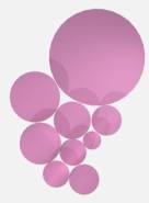
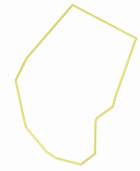
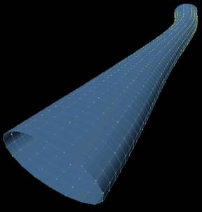
fig 3 some
parametrically defined morphologies
C-Data
Exchange & Fabrication
3D
data exchange between CAAD/CAM/CAE applications has not yet become a standard
process, thus the fabrication and production of the mass custom components is still
considered as a major barrier by most practices due to this missing link of
data flow and relative high cost, and thus avoid exploring further methods for
generating blobs.
Design
Automation using both Emergent & Parametric Generative Design can integrate
the vast data related to A, B, & C by utilising agent based
computation rules where different components are generated from different
groups of agents. Each component is generally unique in size and position in 3D
space. The data generated from the Design Automation process will be digitally
used for Automation Fabrication and thus paving the way for Mass Customization
[ONL 2003].
2.
Conceptual Approach
Swarm
Intelligence: Simple rules will be used and
constantly modified to explore the various behavioural changes within one
swarm, and the general behavioural changes among different swarms and those
changes will result in various generated forms.
Bottom
Up Design: By starting the design stage with the
finest and simplest agents and elements that will gradually generate the whole
complex system.
Biomimetics
Extrapolation: A mix of biomimetic extrapolations will
be demonstrated in one of the experiments to generate a form and its structure
with CAD by using both implicit modelling and explicit programming oriented
modelling.
2.
Computation Principles
 Agent: Based on the principles of Nanotechnology, Swarm
Intelligence, and the Bottom Up approach for generating complex systems
starting by less complex actuators, Agents will be used in groups of various
types to represent various elements of the building envelope and various
elements of the context.
Agent: Based on the principles of Nanotechnology, Swarm
Intelligence, and the Bottom Up approach for generating complex systems
starting by less complex actuators, Agents will be used in groups of various
types to represent various elements of the building envelope and various
elements of the context.
Hill Climbing: as the Agents will be able to learn and adjust by
changing their attraction or repulsion reaction towards other agents according
to how they perceive the changes taking place around them and thus set their 3D
space.
Self Organization Map, as the Agents of the Swarm will be self organized
based on simple rules follow. The will be able to check their neighbouring
Agents of the same Swarm, and the Agents of Neighbouring Swarms and self
organize themselves according to their position in 3D space and the behavioural
rules set for them.
Mapping, Agents will connect each other with elements
according to different rules, thus generating different meshes, tessellations,
patterns, and structural guidelines integrated into the generated envelope.
Fig 4 Netlogo project interface
2.3.
Experiments
The
experiments will be divided into two categories based on two different
conceptual approaches and carried out with different software and programming
languages; Emergent Generative Design using NetLogo 3D-Logo, and Parametric
Generative Design using AutoCAD-Visual Basic for Applications (VBA).
2.3.1
Emergent Generative Design
The
general idea of this approach is that no pre-determined forms are set in the
computation code. Simple abstract rules are given for the agents to follow and
unplanned collective behaviours might be expected to build up from groups of
various types of agents and thus unexpected forms might emerge during the
process.
The
Turtle is the name used in NetLogo 3D to describe an agent. There will
be 4 types of turtles used in the following experiments:
Common
Turtles [CT] agents representing the
surface nodes swarm as grey spheres
Unique
Turtles [UT] agents representing the swarm that
can only dominate the nodes swarm as yellow spheres
Supreme
Unique Turtles [SUT] agents representing the swarm that
can dominate the nodes and unique swarms as red spheres
Edge
Turtles [ET] the agents representing the
connections and mapping generated by the nodes as blue cylinders.
The
force field around each agent is represented with another sphere of the same
but slightly intensity reduced colour.
The
Algorithm:
1.
Each Agent scans every other agent and measures its relationship and distance
to it.
2.
Check own force field and other agent force field and compare to the separating
distance.
3.
If separating distance is greater than force field then travel forward 1
step module, Else repel backwards 1 step module.
4.
Grey CT agent checks for closest neighbouring CT agent and connects it with an
ET agent.
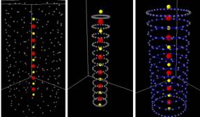
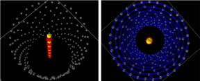
Fig 5 CTs forming spirals ETs forming basket-structure
Trusses emerged
at each floor level
 Trusses emerged at each floor level
Fig
6
The image above shows the attraction and repulsion
relationship between different agents. Notice that the Red SUT Agents are
positioned at each others´ force fields bounding spheres and not being
influenced by other agent types. The Yellow UT Agents are positioned at both
their own and Red SUT Agent’s force field spheres and not being influenced by
the Grey CT Agents. The Grey CT Agents are bounded by their own and Yellow UT
Agents’ force fields and being influenced by the Red SUT force field. The Blue
ET Agents are the cylindrical members connecting the CT Agents. The images in
Fig 5 (representing a building with its core) and bottom Fig 6(representing
blob of blobs) show clearly how different forms, patterns, and structures can
emerge from the simple rules and relationships given to the agents to follow.
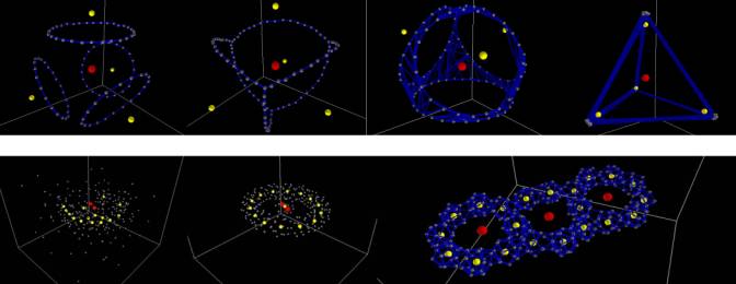
Fig 7 more emergent
morphologies using Net Logo
fig 8 steps 1 – 6
referred to in the text below
2.3.2
Parametric Generative Design
The
concept of generating complex forms and mappings from simple rules will be
maintained as a major part of the whole approach criteria in this section as
well, but there will be no forms or mappings emerging unexpectedly. Everything
will be carefully planned and agents will operate according to well set mathematical
equations, and parameters. The exact position of each agent will not
necessarily be predicted rather than the general form, mapping, and structure
expected to be generated. The agents will still self organize and self learn,
but restricted to follow a well defined order.
The
Algorithm:
1-
the ‘seed’ is set and the node-agents (yellow dots) take the form of a cylinder
and are ready to interact
2-
the source-agents are then inserted (4 red spheres in this case)
3-
each node-agent will scan its surrounding checking its distance with the
neighbouring node-agents simultaneously and the its distance to the
source-agents consecutively
4-
The node-agents will check each others’ results, and will arrange themselves in
order, starting from the closest node-agent to the source-agent (winning node)
down to the furthest one.
5-
The closest node-agent will travel the longest step towards the force-agent.
The step is proportional to the distance between the winning node-agent and the
source-agent. The rest of the node-agents will follow in with shorter steps
according to a distance proportion parametric equation.
6-
Upon each time frame or replication, the node-agents will again check the
distances and rearrange themselves and reduce the magnitude of their next steps
to accommodate the new conditions accordingly. This process as explained
previously is called Self Organization Map and Hill Climbing self learning.
7-
At the end of the final time-frame, the node-agents have already taken their
final positions in 3D space. A skin is generated to wrap the point cloud
determined by the node-agents.
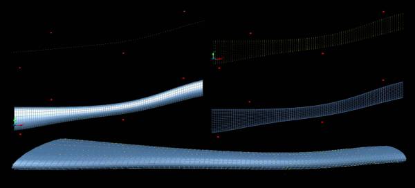
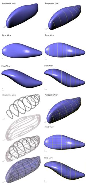
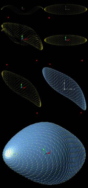 Fig 9
parametrically deformed tubes (force nodes in red)
Fig 9
parametrically deformed tubes (force nodes in red)
Image on the leftfig 10
shows the development of a complex blob from initially a spheroid. . This
node-agents of the spheroid interact with the source fields (red spheres) and
begin following parametric equations and rules and adjust their positions
accordingly.
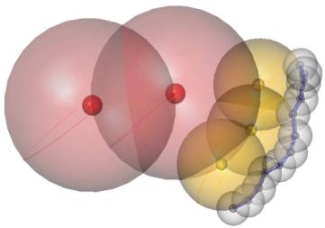
Below,Fig 11 initially
modelled in Rhino, the concept was to develop a blob inspired from both the drop
of water and radial structures like the sea urchin and spider web. The red
source points represent the self weight of the water drop and the blue source
points represent the drag force generated by the wind when freefalling. The
positions taken by the node-agents at the end of the process are wrapped with a
mesh.
Figure 10 complex blob from spheroid
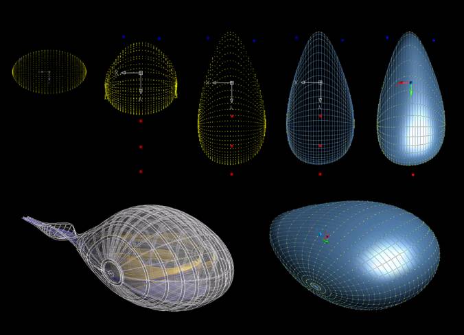
figure 11 see notes above
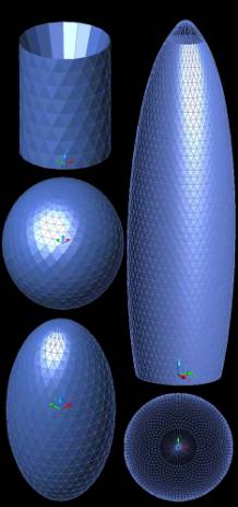 Fig 12
The images left
show clearly the mathematical sequence followed to reach to a form similar to
Fosters’ Swiss RE
The below fig 13
on the right show clearly the
mathematical sequence followed to reach to a form similar to Fosters’ Swiss RE
|
|
Below Fig13 is a series of
tests carried out to see how different meshes with different patterns can take
shapes and forms generated from well defined mathematical equations. Dividing
the agents into different groups within one mesh allows the user to insert more
than one equation into one mesh, thus creating a more complex shape and also
providing more control.
Fig 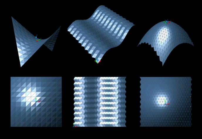
13
References:
Section 1
[1] Ludwig
von Bertalanffy, “General System Theory - Foundations, Development,
Applications”, George Braziller, New York, 1968
[2] Wolfram
Stephen, ”Statistical Mechanics of Cellular Automata”, Reviews of Modern
Physics, 55: 601-644, 1994
[3] Wolfram
Stephen, ”Computation Theory of Cellular Automata.” Communications in
Mathematical Physics, 96: 15-57, 1994
[4] Wolfram
Stephen, “Theory and Applications of Cellular Automata”, Singapore: World
Scientific, 1994
[5] Weiss
P.A., “The basic concept of hierarchic systems”, Hierarchically Organized
Systems in Theory and Practice, New York: Hafner, 1971.
[6] Resnick
Mitchel, “Turtles, Termites and Traffic Jams: Explorations in Massively
Parallel Microworlds”, Complex Adaptive Systems. Cambridge, Massachusetts: MIT
Press, 1997
[7] Bonabeau E., Dorigo M., Theraulaz G., “Swarm Intelligence: From Natural to Artificial Systems”, London, Oxford University Press, 1999
[8] Camazine
S., Deneubourg J.-L., Franks N. R., Sneyd J., Theraulaz G., Bonabeau E.,
“Self-Organisation in biological systems“, Princeton, Princeton University
Press, 2001
[9] Salthe S.N., “Self-organization of / in
hierarchically structured systems”, Systems Research 6: 199-208, 1989.
[10] Salthe
S.N., “Development and Evolution: Complexity and Change in Biology”, Cambridge,
MA: MIT Press. 1993, a.
[11] Ashby W. Ross “Principles of the
Self-Organizing System“ In (Von Foerester and Zopf Jr 1962), pp. 255 - 278.
[12] Holland
John H., “Emergence: From Chaos to Order”, Reading, Massachusetts:
Addison-Wesley, 1998
[13] Holland
John H., “Adaptation in Natural and Artiffcial Systems: An Introductory
Analysis with Applications to Biology, Control, and Artiffcial Intelligence”,
Cambridge, Massachusetts: MIT Press, 1992
section 2
Bob Berkebile and Jason
McLennan, The Living Building-2004
Dennis Dollens, Toward
Biomimetic Architecture, University of Florida • January 2005
ONL, Swarm
Architecture-2003
ONL,, Acoustic
Barrier-2001
ONL, Hyperbodies-2004
Jesper Hoffmeyer, The
Swarming Body-1994
Yahya, Designing
Nature-2004
Yahya, The Miracle in the
Ant-2004
National Nanotechnology
Initiative-2005
David Gordon Collective
Intelligence in Social Insects-2005