Using 3D Virtual Models in Civil Engineering Training: Interacting with the Construction Processes
Prof. A. Z.
Sampaio, PhD; Prof. P. G. Henriques, PhD; Eng. P. S. Ferreira, BEng, Eng. R. P.
Luizi, BEng.
Department of Civil Engineering and Architecture, Technical
University of Lisbon, Lisbon, Portugal.
e-mail: zita@civil.ist.utl.pt, pgameiro@civil.ist.utl.pt
Abstract
The use of virtual reality techniques in the development of educational applications brings new perspectives to the teaching of subjects related to the field of civil construction in Civil Engineering domain. In order to obtain models, which would be able to visually simulate the construction process of two types of construction work, the research turned to the techniques of geometric modelling and virtual reality. The applications developed for this purpose are concerned with the construction of a cavity wall and a bridge. These models make it possible to view the physical evolution of the work, to follow the planned construction sequence and to visualize details of the form of every component of the works. They also support the study of the type and method of operation of the equipment necessary for these construction procedures. These models have been used to distinct advantage as educational aids in first-degree courses in Civil Engineering.
1. Introduction
Normally, three-dimensional geometric models, which are used to present architectural and engineering works, show only their final form, not allowing the observation of their physical evolution. In the present study, two engineering construction work models were created, from which it was possible to obtain three-dimensional (3D) models corresponding to different states of their form, simulating distinct stages in their construction. The use of techniques of virtual reality in the development of these educational applications brings new perspectives to the teaching of subjects in the area of civil engineering. The work described here makes up part of two on-going research projects at ICIST: Automatically generating model of the graphic representation of bridges [1], A. Zita Sampaio (main research) and Virtual reality in optimisation of construction project planning [2], Pedro G. Henriques (coordinator).
The visual simulation of the construction process needs to be able to produce changes to the geometry of the project dynamically. It is then important to extend the usefulness of design information to the construction planning and construction phases. The integration of geometrical representations of the building together with scheduling data is the basis of 4D (3D + time) models in construction domain. 4D models combine 3D models with the project timeline [3]. 4D-CAD models are being used more and more frequently to visualize the transformation of space over time. To date, these models are mostly purely visual models. On a construction project, a 4D-CAD environment enabled the team, involved in the project, to visualize the relationships between time (construction activities) and space (3D model of the project) [4].
In order to create models, which could visually simulate the construction process, the authors turned to techniques of geometric modelling and virtual reality (VR). The applications developed for this purpose refer to the construction of a masonry cavity wall and a bridge. These models make it possible to show the physical evolution of the work, the monitoring of the planned construction sequence, and the visualization of details of the form of every component of each construction. They also assist the study of the type and method of operation of the equipment necessary for these construction procedures. The virtual model can be manipulated interactively allowing the user to monitor the physical evolution of the work.
One of the applications developed corresponds to the model of a masonry cavity wall, one of the basic components of a standard construction. To enable the visual simulation of the construction of the wall, the geometric model generated is composed of a set of elements, each representing one component of the construction. Using a system of virtual reality technologies, specific properties appropriate to the virtual environment are applied to the model of the wall. Through direct interaction with the model, it is possible both to monitor the progress of the construction process of the wall and to access information relating to each element, namely, its composition and the phase of execution or assembly of the actual work, and compare it with the planned schedule. This model had been used to distinct advantage as an educational aid in Civil Engineering degree course modules.
The second model created allows the visual simulation of the construction of a bridge using the cantilever method. The geometric model of the bridge deck was created through a bridge deck modelling system. A system of virtual reality was used to program the visual simulation of the bridge construction activities. Students are able to interact with the model dictating the rhythm of the process, which allows them to observe details of the advanced equipment and of the elements of the bridge. The sequence is defined according to the norms of planning in this type of work. The aim of the practical application of the virtual model of bridge construction is to provide support in those disciplines relating to bridges and construction process both in classroom-based education and in distance learning based on e-learning technology.
2. Case study 1: Construction of a masonry cavity wall
Described here are the processes both of the modelling of an exterior wall of a standard building and of the association of virtual properties with the created model, the intended outcome being the interactive exhibition of its construction [5]. The model of the masonry cavity wall, including the structure of the surrounding reinforced concrete and the elements in the hollow area (bay elements), was created using a three dimensional graphic modelling system in widespread use in planning offices, namely, AutoCAD. The virtual environment was applied to the model through the computer system EON Studio [6].
2.1 Geometric modeling of the wall’s elements
The representation of this model of an exterior wall of a conventional building comprises the structural elements (foundations, columns and beams), the vertical filler panels and two bay elements (door and window). The structural elements of the model were created with parallelepipeds and were connected according to their usual placement in building works. Because this is an educational model, the steel reinforcements were also defined. In the model, the rods of each reinforcement are shown as tubular components with circular cross-section (Figure 1).
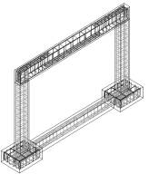
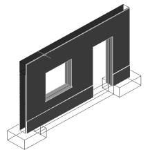
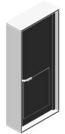
Figure 1: Phases in modelling the masonry wall
The type of masonry selected corresponds to an external wall formed by a double panel of breezeblocks, 11 cm, wide with an air cavity, 6 cm, wide (Figure 1). Complementary to this, the vertical panels were modelled, these comprising: the thermal isolation plate placed between the brick panels, the plaster applied to the external surface of the wall, the stucco applied on the internal surface, two coats of paint both inside and out and the stone slabs placed on the exterior surface. Finally, two usual bay elements (Figure 1), a door and a window, were modelled. The completed model was then transferred to the virtual reality system EON (as a 3ds drawing file).
2.2 Definition of the virtual environment in the evolution of a construction
Figure 2 presents the main window of the EON system. The sub-window to the left contains a table of nodes or actions (of movement, sensors etc) available in this system. The centre sub‑window is designated a simulation tree: the objects making up a given scenario are presented in it, and the links between each object or group and the actions to be taken associated to each of them are also shown. It is therefore, through the use of this window that the simulation of the desired virtual action is programmed. In the sub-window on the right the links between the various nodes are established thus defining a network. In this network the nodes where the links originate and terminate are identified, as is the means of setting each action in motion.
In this system, the visual simulation of the building process of the wall, following a particular plan, was programmed. For this effect, 23 phases of construction were considered. The order in which components are consecutively exhibited and incorporated into the virtual model, translates into the method of the physical evolution of the wall under construction.
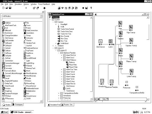
Figure 2: The main window of the EON Studio system
During the animation, the student can control the length of time that any phase is exhibited and observe the model using the most suitable camera and zoom positions for a correct perception of the details of construction elements. It is possible to highlight the component incorporated at each new phase and to examine it in detail (Figure 3).
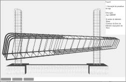
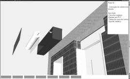
Figure 3: Exhibition of phases in building evolution.
Included, under the window in which the virtual scene is exhibited, is a bar, which shows the progress of the construction. Throughout the animation, the bar is filled, progressively, with small rectangles symbolizing the percentage built at the time of the viewing of that particular phase, in relation to the completed wall construction (Figure 3).
Simultaneously, with the visualization of each phase, a text is shown (in the upper right corner of the window, Figure 4) giving data relating to the stage being shown, namely, its position within the construction sequence, the description of the activity and the characterization of the material of the component being incorporated.
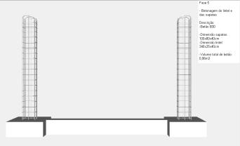
Figure 4: Presentation of text describing the exhibited phase.
3. Case study 2: Construction of a bridge deck
Throughout the bridge research project, a system of computer graphics was used, a system that enables the geometric modelling of a bridge deck of box girder typology [1]. This system was used to generate, 3D models of deck segments necessary for the visual simulation of the construction of the bridge [7]. In addition to the 3D model of each segment, models of the pillars, form travellers, abutments and false work were made. The attribution of virtual properties to the model of the bridge was implemented by using the EON Studio.
The North Viaduct of the Quinta Bridge [8] in Madeira, Portugal, was the case selected for representation in the virtual environment. In cross-section, the deck of the viaduct shows a box girder solution and its height varies parabolically along its three spans. The most common construction technique for this typology is the cantilever method of deck construction. This method starts by applying concrete to a first segment on each pillar, the segment being long enough to install on it the work equipment. The construction of the deck proceeds with the symmetrical positioning of the segments starting from each pillar. The continuation of the deck, uniting the cantilever spans, is completed with the positioning of the closing segment.
3.1 Modeling the elements of the construction scenario
The spans were created through the use of the representational system for bridges mentioned above. Geometric description can be entered directly into the deck-modelling program. To achieve this, the developed interface presents diagrams linked to parameters of the dimensions, so facilitating the description of the geometry established for each concrete case of the deck. The image included in Figure 5 shows the interface corresponding to the cross-section of the deck of the example.
The description of the longitudinal morphology of the deck and the geometry of the delineation of the service road, serving the zone where the bridge is to be built is carried out in the same way. The configuration and the spatial positioning of each are obtained with a high degree of accuracy. Using the data relating to the generated sections, the system creates drawings and 3D models of the deck. To obtain the definition of the deck segment models, consecutive sections corresponding to the construction joints are used. The configuration presented by the segment models is rigorously exact. Figure 5 shows one of the segments of the deck.
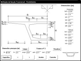
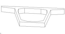
Figure 5: Interface of the description of the cross-section of the deck and the projection of the model of one of the segments.
To complete the model of the bridge, the pillars and abutments were modelled using the AutoCAD system. Based on research in the literature concerning abutments for the typology of box-girder decks, a model was created as shown in Figure 6. Then followed the modelling of the advanced equipment, which is composed not only of the form traveller, but also the formwork adaptable to the size of each segment, the work platforms for each formwork and the rails along which the carriages run (Figure 6).
Figure 6: 3D models of the abutments, false work, scaffolding and advanced equipment.
As, along with the abutments, the deck is concreted with the false work on the ground, the scaffolding for placement at each end of the deck was also modelled (Figure 6). Terrain suitable for the simulation of the positioning of the bridge on its foundations was also modelled.
3.2 Programming the virtual construction animation
Once all the 3D models of the construction scenario had been generated, they were transposed, in 3ds data file format, to the virtual reality system. The definition of the construction sequence is based on a counter, which determines the next action when a mouse button is clicked. This connection is prescribed through a network of connections.
The first action consists of the insertion of the pillars in the initial scenario, which is composed solely of the landscape. The next step is to place one of the segments on top of each of the pillars (Figure 7). After this, a form traveller is placed on each segment. For the simulation of the first cantilever segment (in each span), the four form travellers, the corresponding work platforms and the formwork components are included in the scenario (Figure 7).
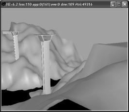
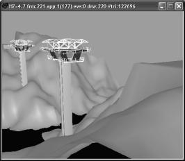
Figure 7: Placing the initial pillars and segments and the advanced equipment.
Once the first segments have been concreted, the construction of the cantilevered deck takes place. The construction of the deck is defined symmetrically in relation to each pillar and simultaneously. In each phase, two pairs of segments are defined. For each new segment the following steps are established: raising the form traveller; moving the rails in the same direction as the construction (relocating them on the latest segment to have been concreted); moving the form traveller on the rails, positioning it in the zone of the next segment to be made; concrete the segment (Figure 8). The user can observe all these stages. Finally, the zone of the deck near the supports is constructed, the false work resting on the ground (Figure 8).
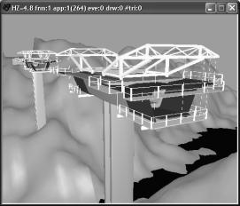
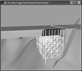
Figure 8: Movement of the advanced equipment and concreting above the false work near the abutment.
Moving the camera closer to the model of the bridge and applying to it routes around the zone of interest, it is possible to visualize the details of the form of the components involved in the construction process. In this way, the student can interact with the virtual model, following the sequence specifications and observing the details of the configurations of the elements involved.
4. Learning aspects
The models are actually used in face-to-face classes of disciplines of Civil Engineering curriculum: Technical Drawing (1st year), Construction Process (4th year) and Bridges (5th year). The teacher interacts with the model showing the sequence construction and the constitution of the modelled building element.
As in Technical Drawing, students have to define and represent structural plants using architectural layouts, they better understand the relations between the architectural configurations and the structural elements in a building, following the exhibition of the wall’s construction. In Construction Process and Bridges, in order to prepare students to visit real work places, the teacher shows the construction animation and explains some aspects of the construction process of the wall or the bridge that in the work place they are going to see.
Essentially, the models are used to introduce new subjects. The students reflected on their evaluation works a better understanding of subjects concerning structures, bridges and construction. For instance, in a structural plant the representation of columns and beams is now better aligned. Or, the students’ reports concerning visits at work places include now some aspects shown in the virtual models.
The students can also interact with those models. For that, the models were posted on the Internet pages of undergraduate Civil Engineering. The student will be able to interact with the application EonX, which can be accessed at http://download. eonreality.com.
5. Conclusions
It has been demonstrated, through the examples presented here, how the technology of virtual reality can be used in the elaboration of teaching material of educational interest in the area of construction processes.
The models generated represent building in two standard situations. The student can interact with the virtual model in such a way that he can set in motion the construction sequence demanded by actual construction work, observe the methodology applied, analyse in detail every component of the work and the equipment needed to support the construction process and observe how the different pieces of a construction element mesh with each other and become incorporated into the model.
These models are used in disciplines involving construction in courses in Civil Engineering and Architecture administered by the Higher Technical Institute of the University of Lisbon. They can be used in classroom-based education and in distance learning supported by e-learning technology.
6. Acknowledgements
The research projects involved in this work are financially supported by the Foundation of Science and Technology (FCT) through funds attributed by the FEDER program.
References
[1]
A.Z.
Sampaio, A. Reis, H. Braz, L. Silva, “Project program report: Automatically
generating model of the graphic representation of bridges”, POCTI/1999/ECM/
36328, ICIST/FCT, Lisbon, 1999.
[2]
P.G.
Henriques, A.Z. Sampaio, J. Bento, H. Braz, “Project program report: Virtual
reality in optimisation of construction project planning”, POCTI/1999/ECM/
36300, ICIST/FCT, Lisbon, 1999.
[3]
J.
Leinonen, K. Kähkönen, A. Retik, “New construction management practice based on
the virtual reality technology”, in book “4D CAD and Visualization in Construction:
Developments and Applications”, editors Raja R.A. Issa, Ian Flood William J.
O’Brien. Ed. A.A. Balkema Publishers, 2003, pp. 75-100.
[4]
K.
Liston, M. Fischer, T. Winograd, “Focused sharing of information for
multi-disciplinary decision making by project teams”, in International Journal
Itcon, Vol. 6, 2001, pp. 69-82.
[5]
A.Z.
Sampaio, P.G. Henriques, P.S. Ferreira, “A virtual environment tool applied to
visualize construction processes”, in Proceeding of TP.CG.04 – Theory and
Practice of Computer Graphics 2004 Conference, Bournemouth (U.K.), June 8‑10,
2004, pp. 78-85.
[6]
“Introduction
to working in EON Studio”, EON Reality, Inc. 2003.
[7]
A.Z.
Sampaio, “Definition of a bridge deck geometrical modelling process to automate
design graphical representations”, in Proceeding of IKM 16th International
Conference on the Applications of Computer Science and Mathematics in
Architecture and Civil Engineering, Weimar (Germany), June 10-12, 2003 abstract
pp. 62 - CDROM 6 pgs.
[8]
“Graphical
documentation of the design of North Viaduct of the Quinta Bridge - 1st phase”,
GRID Planning office, Lisbon, 1995.