Aesthetic
Evolutionary Design with Data Flow Networks
Matthew Lewis, MSc, PhD candidate.
Advanced
Computing Center for the Arts and Design, Ohio State University, Columbus, USA.
e-mail: mlewis@cgrg.ohio-state.edu
Abstract
For a little over a decade, software has been created which allows for the design of visual content by aesthetic evolutionary design (AED). The great majority of these AED systems involve custom software intended for breeding entities within one fairly narrow problem domain, e.g., certain classes of buildings, cars, images, etc. Only a very few generic AED systems have been attempted, and extending them to a new design problem domain can require a significant amount of custom software development. High-end computer graphics software packages have in recent years become sufficiently robust to allow for flexible specification and construction of high-level procedural models. These packages also provide extensibility, allowing for the creation of new software tools. One component of these systems that enables rapid development of new generative models and tools is the visual data flow network. One of the first CG packages to employ this paradigm was Houdini. A system constructed within Houdini that allows for very fast generic specification of evolvable parametric prototypes is described. The real-time nature of the software, when combined with the interlocking data networks, allows not only for vertical ancestor/child populations within the design space to be explored, but also allows for fast horizontal exploration of the potential population surface. Several example problem domains will be presented and discussed.
1. Introduction
Aesthetic evolutionary design (AED) systems allow non-expert designers to “discover” interesting design solutions via an exploration-based, rather than construction-based, interface. Using the extensible 3D modeling and animation package Houdini [22], a system (referred to as Metavolve) is under construction that allows for the evolution of arbitrary parametric visual entities. Once the parametric object to be evolved (called a prototype) is created by a user familiar with Houdini modeling, the prototype can be dropped into the evolution interface and the parameter space can be explored for interesting design solutions (Figure 1).
Houdini was one of the earlier animation and modeling systems to rely almost exclusively on data flow networks as an interface. A simple “cartoon face” prototype has been created which will illustrate how these networks can be used for both representing prototypes as well as evolving populations of individuals. Cartoon faces serve as an excellent testing and demonstration domain for AED, not only because they can be created from a few primitive circles, but also because of their substantial expressive and associative potential resulting from only a small number of parameters.
AED can provide a very worthwhile design exploration tool for many design domains as can be seen by the numerous systems that have made use of the technique. Following Dawkins' biologically inspired Biomorphs program [7] that evolved 2D insect-like drawings, Todd and Latham [26] and Sims [23] were the first to evolve computer graphics objects via aesthetic selection. Images [10][29][12], sculpture [25], architecture [4][6][19][24], image processing [17], consumer products [3][8][11], human bodies [15] and faces [2][5] and character motion [1][16][30] have all been evolved by aesthetic selection. Many others have made systems for evolving images and form using variations on the techniques employed by Sims, Todd, and Latham. Links to a number of these can be found at [14]. Rowbottom provides a detailed overview of the functionality of many of these as well [20].
There have been a few generic systems for solving general AED problems as well. Rowley created a system that combined a toolkit for displaying and judging image based phenotypes, with a general system for mutating and crossbreeding expression based genotypes. Different “modules” could be written for different problem spaces, with each module providing domain specific implementations of mutation, crossbreeding, and image generation. Modules for evolving Sims-style expression and fractal-based images were produced [21]. Todd and Latham created a generic evolutionary design system called PC Mutator capable of interfacing with external existing Windows based software such as paint programs. Once parametric models are built (e.g., for designing cartoon faces), PC Mutator sends commands to the external application to create a population of instances of the model. The external application generates images of the individuals, which are then passed back to PC Mutator for display [27][28]. Pontecorvo and Elzenga also are developing an environment for generic evolutionary design called ED Workbench. Their primary focus is the facilitation of product design [9][18].
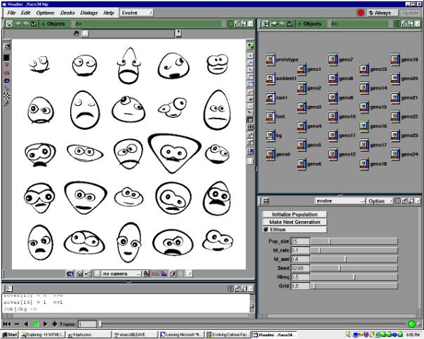
Figure 1: Houdini interface, Metavolve custom panel, and an initial face population
2. Interface
As shown in Figure 1, the AED process begins with an initial population of arbitrary size. In addition to controlling the size of the current population, the interface components in the lower right corner of Figure 1 allow for the control of standard evolution parameters such as mutation rate, population size, and crossover frequency. The user interactively selects any number of the "best" individuals in the population for breeding. The selected individuals form the mating pool for the next generation. For example, from the population in Figure 1, three individuals were selected. They appear as the first three faces on the left in the bottom row of Figure 2. The remaining 22 faces are the offspring of these three selected faces. Each offspring was created by combining the genes of a randomly chosen pair of the selected parents.
When offspring are produced, varying degrees of mutation (random adjustment of selected gene values) can be performed. In Figure 3, the entire population consists of slightly mutated copies of the face in the bottom left corner. The same face is mutated much more to produce the population in Figure 5. Selecting parents and producing new generations can be continued until the population ultimately converges (Figure 4).
|
Figure 2: Offspring |
Figure 3: Low mutation |
|
Figure 4: Convergence |
Figure 5: High mutation |

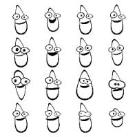
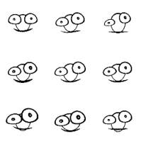
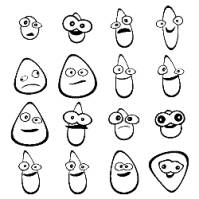
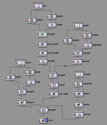
Figure 6: Cartoon face prototype
3. Prototype Representation
The cartoon face prototype presented consists of a stack of black and white disks, each of which has been moved and deformed from its default position and shape as a result of the values of its genes. In a data flow network-based system, geometric objects like these cartoon faces are constructed using a directed acyclic graph (DAG). The DAG’s leaf nodes are generally geometric primitives, in this case, circles. The remaining nodes all modify the geometric data in some way (depending on each node’s type) as the data “flows” from the graph’s leaves to its root at the bottom. In the face network shown in Figure 6, six different types of nodes are used (referred to in Houdini as SOPs or surface operators). The leaves at the top of the network image are circle SOPs. The circle geometry they produce flows into material SOPs which color each circle either black or white. Notice that the output of the circle SOPs can be split, creating two data streams that are later merged (via a merge SOP) further down the network. The remaining SOP types used are transform SOPs, which scale, rotate, and translate geometry, a copy SOP, used to duplicate the eye, and twist SOPs that bend the geometry.
The circle, transform, and twist SOPs each have their parameters set based on each individual’s normalized gene values. Each individual has associated with it 17 genes (range [0..1]) each of which affects one property in the individual’s copy of the prototype network. Within each SOP that references a gene, an expression is used to access the correct normalized gene value and map it into a range appropriate for the parameter in question:
fit(chopci("/ch/evolve/genotypes",opdigits(".."),10),0,1,-20,20)
In this case, the amount that the input geometry (e.g., the face’s mouth) is bent by one of the twist SOPs is determined by looking up the value of that face’s 10th gene and remapping the gene’s value from [0..1] into [-20..20].
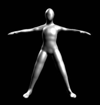
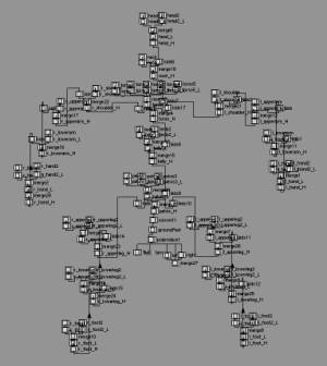
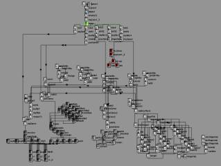
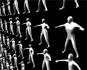
A more complex prototype was recently completed which used 96 genes to evolve human figure geometry (Figure 7 and Figure 10). The geometry is created by a hierarchy of 35 blending ellipsoids, each of which can be individually scaled, oriented, and positioned. The network representing this parametric geometry is shown in Figure 8 to give an idea of the relative complexity. The prototype also uses a parameter network (Figure 9) that combines the 96 genes into lower level geometric transformation attributes. See [15] for details.
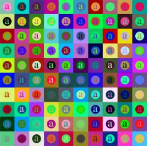
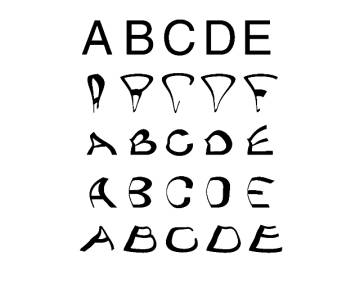
Figure 11 and Figure 12 show two more examples of simple prototypes. Figure 11 displays an initial population of an extremely simple prototype that consists of a letter in front of a circle in front of a square. The nine genes provide RGB color values for each of the three prototype elements. Figure 12 shows a prototype that is currently under development. Each row represents a different font, with each letter in the font being similarly deformed by a grid of localized magnet SOPs. Suitable parameterizations for the deformation of the letters are currently being investigated by a collaborator, Ian Butterfield.
|
Figure 11: Color combination population |
Figure 12: Font population |
4. Evolution
As was mentioned above, a custom interface panel (shown in the lower right part of Figure 1) is used to control evolution parameters such as population size, mutation, and crossover. This interface panel also contains the button the user presses to trigger the generation of the next population (after the “favorite” individuals have been selected). The network shown in Figure 13 is used to produce the genes for the initial population as well as those for subsequent generations.
Unlike the geometry manipulating SOPs of Figure 6, Figure 13 employs CHOPs or “channel operators”. It is again a data flow network, with generator nodes at the graph’s leaves producing data that flows through the network of data manipulators to a root node. In a CHOP network the data consists of channels that store arrays of values. For each individual in a population, a channel is created, and each channel consists of the values for that individual’s genes. Each cartoon face, for example, is represented by a single channel having 17 genes.
Initially, a noise CHOP is used to generate a channel of random genes for each individual in the population. The genes for an initial population of nine individuals are shown in Figure 14.
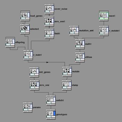
Figure 13: Evolution network
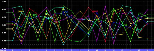
Figure 14: Genes of initial population
When the Make Next Generation button in the custom panel is pressed, a script is called which stores the genes of the individuals in the current generation in a file that is then read by a file CHOP (labelled “load_genes”) at the top of the CHOP network. The individuals selected by the user for breeding are also noted by the script, and a delete CHOP (labelled “selected”) just below the file CHOP filters out the non-selected gene channels, leaving only those individuals selected to serve as the mating pool (or parents).
For each offspring to be generated, a series of chops determines where crossovers will occur between the chromosomes of the offspring's parents during the mating/copying process. Figure 15 shows the crossover channels produced for four of the offspring. The gene locations at which crossover should occur correspond to the values that are set to a value of one.
The above crossover channels, the selected parent channels, and initially empty offspring channels all enter a mate CHOP[1]. This CHOP chooses random pairs of parents from the mating pool, uses the crossover channels to combine the parents’ genes, and copies the combined genes into the offspring gene channels. The mate CHOP's output provides the genes for the newly created offspring, as shown in Figure 16 (with a population of nine). Convergence of some of the gene values can be observed (e.g., genes 5, 6, and 12).
After the population of offspring is produced, depending on the mutation rate and amount chosen by the user, some number of offspring genes may be mutated, i.e., changed randomly. Another series of chops randomly generates a channel for each offspring that determines which genes should be mutated, and by how much. Figure 17 shows the mutation amounts for each offspring’s genes (the channels centered at a value of zero at the bottom) that are added to the offspring of Figure 16 to yield the mutated offspring shown in the upper half of Figure 17.
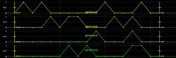
Figure 15: Crossover points
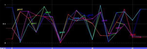
Figure 16: Offsprings’ genes
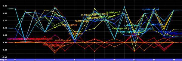
Figure 17: New population’s genes and mutation channels
The real-time nature of the data flow networks yields an additional avenue of design space exploration. Assuming the individuals can be generated quickly enough from a corresponding set of genes, not only is it possible to explore the parameter space vertically by examining multiple generations, it also becomes possible to explore the space of possibilities horizontally by adjusting the evolution control sliders (e.g., mutation amount). Changing the evolution parameters optionally modifies the current generation, displaying the population that would have been produced given those settings. This allows the user to explore what the current generation would look like with more or less mutation, a higher degree of crossover, a different population size, etc.
5. Conclusion
The use of data flow networks permits faster construction and experimentation with new problem domains (prototypes) than if a new procedural model needed to be programmed for each new domain. CHOP networks permits visualization of genetic differences at a glance in a given population, providing a unique method for evaluation of both the evolutionary techniques chosen, as well as the prototype representation schemes.
The next two problem domains to be ported into this system will be a parametric model for evolving architecture for real time game environments (Figure 18) and a prototype for evolving painterly images (Figure 19). Both of these prototypes are currently functioning as command line based Perl scripts but porting them into Houdini and Metavolve will allow all of Houdini’s modeling and design algorithms to be employed.
Thanks to Wayne Carlson, Antoine Durr, Lawson Wade, and Side Effects Software for their assistance and support. Permission to display elements of the Houdini interface in figures 1, 6, 8, 9, 13-17 was granted by Side Effects Software, Inc. Permission to display the screenshot of the Quake III Arena engine and textures in Figure 18 was granted by id Software, Inc. All product names mentioned are trademarks of their respective holders.
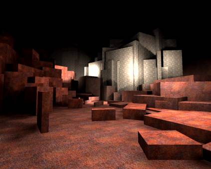
Figure 18: Parametric game environment prototype (textures by id Software, Inc.)
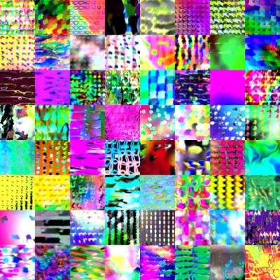
Figure 19: Initial population of 64 parametric images
References
[2]
Baker, Ellie. “Evolving Line Drawings”
in Proceedings of the Fifth International Conference on Genetic Algorithms. Morgan
Kaufmann, 1993.
[3]
Bentley,
Peter. Evolutionary Design by Computers. Morgan
Kaufmann, 1999.
[7] Dawkins, Richard. The Blind Watchmaker, Penguin Books, 1986.
[8] Emergent Design. “Chair Farm”, 2000, http://www.emergent-design.com/dyn/chair.html
[12] Hemert, Jano van. Mondriaan Art by Evolution, 2000, http://www.wi.leidenuniv.nl/~jvhemert/mondriaan
[13] Lewis, Matthew. "Metavolve Home Page". 2000,
http://www.cgrg.ohio-state.edu/~mlewis/AED/Metavolve/
[14] Lewis, Matthew. "Visual Aesthetic Evolutionary Design
Links". 2000, http://www.cgrg.ohio-state.edu/~mlewis/aed.html
[19]
Rosenman, M. A. “An Exploration into Evolutionary Models for
Non-routine Design” in Evolutionary Algorithms in Engineering Applications,
Eds. Dasgupta, D. and Michalewicz, Z., Springer-Verlag,
1997.
[22] Side Effects Software. Houdini. 2000, http://www.sidefx.com
[23] Sims, Karl. "Artificial evolution for computer graphics", ACM Computer Graphics 25(4), 1991.
[26] Todd, Stephen and William Latham. Evolutionary Art and Computers. Academic Press, 1992.
[28] Todd, Stephen. Personal communication. August, 2000.
[29] Ventrella, Jeffrey. Tweaks. 2000, http://www.ventrella.com